


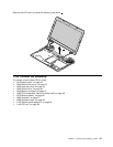
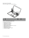
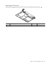
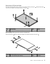

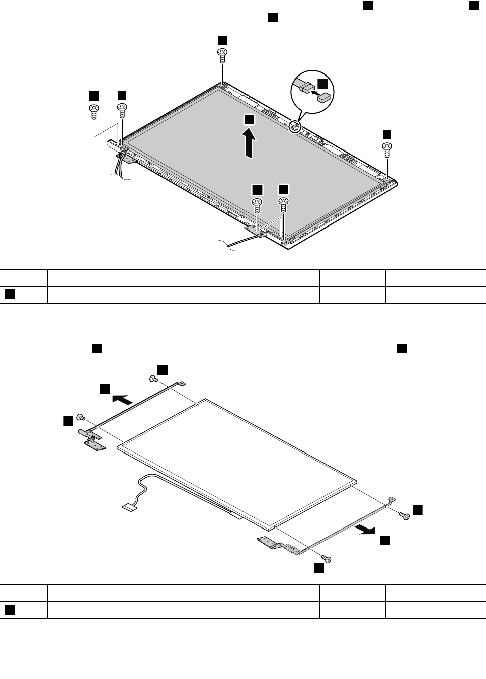
Removal steps of LCD panel and hinges
Disconnect the integrated camera connector in the direction shown by the arrow 1 . Remove the screws 2 .
Then lift the LCD panel in the direction shown by the arrow 3 .
2
2
2
2
2
2
3
1
Step Screw (quantity) Color
Torque
1
M2 × 3 mm, at-head, nylon-coated (6)
Black
1.6 kgfcm
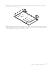
When installing: Make sure that the connector is attached rmly.
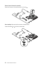
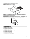
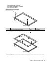
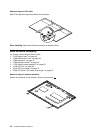
Remove the screws 4 and then remove the hinges in the direction shown by the arrows 5 .
5
4
4
4
4
5
Step Screw (quantity) Color
Torque
4
M2 × 3 mm, at-head, nylon-coated (4)
Black
1.6 kgfcm
Chapter 7. Removing and replacing a FRU 75