


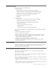
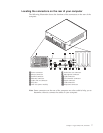
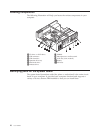
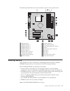
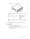

The
following
illustration
shows
the
locations
of
parts
on
the
system
board.
1
Microprocessor
11
SATA0
connector
2
DIMM
connector
1
12
Front
panel
connector
3
DIMM
connector
2
13
Clear
CMOS/Recovery
jumper
4
DIMM
connector
3
14
Battery
5
DIMM
connector
4
15
Front
panel
audio
connector
6
Power
connector
16
PCI
slot
3
7
Diskette
drive
connector
17
PCI
slot
2
8
Primary
IDE
connector
18
PCI
slot
1
9
Secondary
IDE
connector
19
AGP
slot
(some
models)
10SATA1
connector
20
12v
power
connector
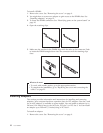
Installing
memory
Your
computer
has
four
connectors
for
installing
dual
inline
memory
modules
(DIMMs)
that
provide
up
to
a
maximum
of
4.0
GB
of
system
memory.
When
installing
DIMMs,
the
following
rules
apply:
v
System
memory
is
divided
into
two
channels
(channel
A
and
B).
DIMM
connectors
1
and
2
are
channel
A,
and
DIMM
connectors
3
and
4
are
channel
B.
v
If
DIMM
connectors
1
and
3
(or
2
and
4)
are
filled
with
the
same
technology
and
size
of
memory,
the
system
operates
in
dual
channel
mode.
v
Use
2.5
V,
184-pin,
double
data
rate
synchronous
dynamic
random
access
memory
(DDR
SDRAM).
v
Use
128
MB,
256
MB,
512
MB
or
1.0
GB
DIMMs
in
any
combination.
v
DIMMs
are
38.1
mm
(1.5
inches)
in
height.
Note:
Only
DDR
SDRAM
DIMMs
can
be
used.
Chapter
1.
Types
8149,
8177,
and
8178
11