


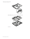
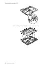
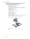
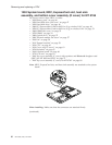
1220 System board, MDC, PC Card slot, and bottom cover
assembly (D cover) for MT 0689 and 0768
For access, remove these FRUs, in order:
v “1010 Battery pack” on page 46
v “1020 Hard disk drive slot cover” on page 47
v “1030 Hard disk drive” on page 48
v “1040 PCI Express Mini Card for 802.11 a/b/g wireless LAN” on page 49
v “1050 PCI Express Mini Card for 802.11 a/b/g/n wireless LAN” on page 51
v “1060 DIMM slot cover” on page 53
v “1070 DIMM” on page 54
v “1080 Optical drive” on page 55
v “1090 Thermal module slot cover” on page 57
v “1100 Fan” on page 58
v “1110 Thermal module” on page 59
v “1120 CPU” on page 62
v “1130 Cover, strip (E cover)” on page 63
v “1150 Keyboard” on page 65
v “1160 Function board” on page 68
v “1170 LCD unit” on page 69
v “1180 Top cover assembly (C cover) with speakers and Bluetooth daughter card
(BDC) for MT 0689 and 0768” on page 75
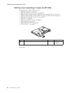
v “1190 Top cover assembly (C cover) for MT 0769” on page 80
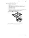
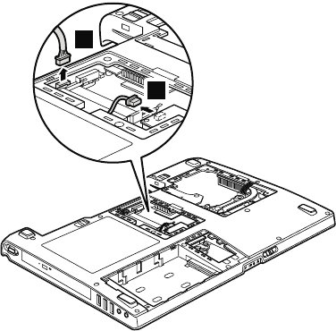
Note:
MDC and PC Card slot are attached to the system board.
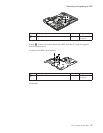
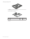
1
2
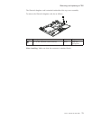
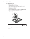
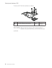
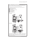
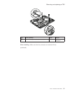
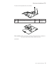
When installing: Make sure that the connectors are attached firmly.
(continued)
Removing and replacing a FRU
86 MT 0689, 0768, and 0769