


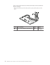
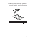
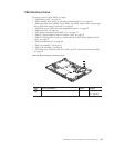
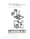
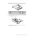
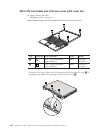
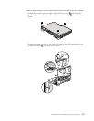
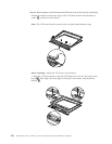
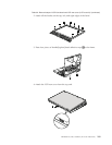
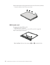
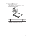

Table 29. Removal steps of system board, PC Card/Express card slots assembly or PC
Card/Smart card slots assembly or PC Card/4-in-1 media reader slot assembly
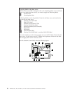
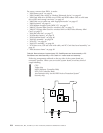
Following components soldered on the top side of the system board are
extremely sensitive. When you service the system board, avoid any kind of
rough handling.
a CPU
b Video chip
c MCH (Memory Controller Hub)
d ICH (I/O Controller Hub)
e Accelerometer chip for the HDD Active Protection System
™
f Security chip
ef
a
b
c
d
For access, remove these FRUs, in order:
v “1010 Battery pack” on page 61
v “1020 Ultrabay Slim device or Ultrabay Enhanced device” on page 62
v “1030 Hard disk drive (HDD) cover, HDD, and HDD rubber rails or solid state
drive (SSD) and storage converter” on page 63
v “1040 Palm rest or palm rest with fingerprint reader” on page 65
v “1060 Keyboard” on page 69
v “1070 Modem daughter card (MDC-1.5)” on page 71
v “1080 PCI Express Mini Card for wireless LAN” on page 73
v “1090 PCI Express Mini Card for wireless WAN or Intel Turbo Memory Mini
Card” on page 75
v “1100 SIM card slot” on page 77
v “1110 Backup battery” on page 79
v “1120 Keyboard bezel” on page 80
v “1140 Fan assembly” on page 84
v “1150 CPU” on page 89
v “1160 LCD assembly” on page 90
v “1170 Base cover, USB sub card with cable, and PC Card slots bezel assembly” on
page 93
v “1180 Structure frame” on page 99
104 ThinkPad T61, R61, and R61i (14.1-inch widescreen) Hardware Maintenance Manual