


87
Lenovo IdeaPad U300/U300s/U400
1090 LCD unit (U400)
For access, remove these FRUs in order:
• “1010 Base cover (U400)” on page 74
• “1020 Battery pack (U400)” on page 76
• “1030 Hard disk drive (U400)” on page 77
• “1040 PCI Express Mini Card for wireless LAN (U400)” on page 78
• “1050 System board (U400)” on page 80
• “1060 USB board and HDD board (U400)” on page 82
• “1070 Speakers and microphone (U400)” on page 84
• “1080 Optical drive (U400)” on page 86
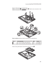
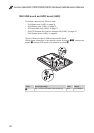
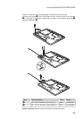
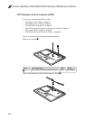
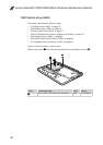
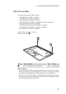
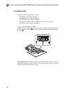
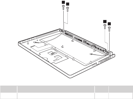
Figure 9. Removal steps of LCD unit
Remove four screws
1
.
1
1
1
1
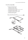
Step Screw (quantity) Color Torque
1
M2 × 6 mm, at-head, nylok-coated (4) Black 1.6 ± 0.24 kgfcm
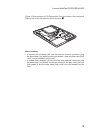
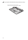
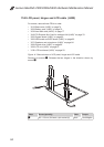
When installing:
Route the antenna cables along the cable guides. As you route the cables, •
make sure that they are not subjected to any tension. Tension could cause
the cables to be damaged by the cable guides, or a wire to be broken.
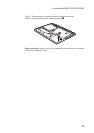
Make sure that the LCD connector is attached rmly and make sure that you •
do not pinch the antenna cables when you attach the LCD assembly. Route
the LCD cable along the cable guides.