


Lenovo V570/B570 Hardware Maintenance Manual
50
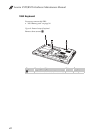
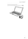
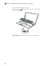
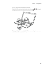
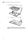
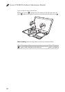
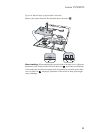
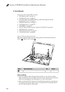
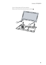
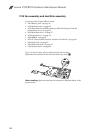
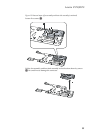
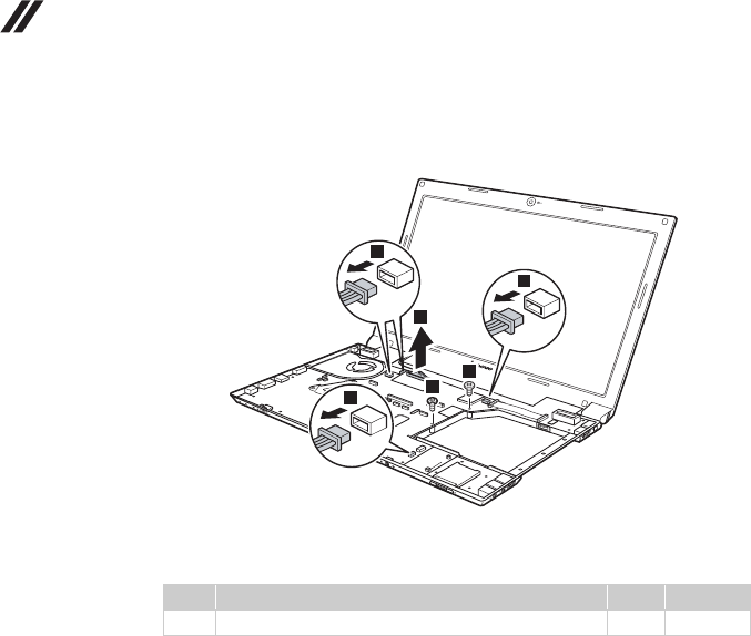
Figure 10. Removal steps of system board
Remove two screws . Unplug the LCD connector in the direction shown by
arrow , and four microphone connectors in the direction shown by arrow .
When installing: Make sure that all the connectors are attached firmly.
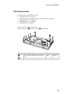
Step Screw (quantity) Color Torque
M2 × 6 mm, flat-head, nylok-coated (2) Black 2.5 kgfcm
a
b
c
2
1
1
1
3
3
3
a