


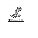
Table 24. Removal steps of system board, DC-in connector, fan, and ExpressCard slot
assembly for ThinkPad X200, X201, and X201i (continued)
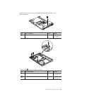
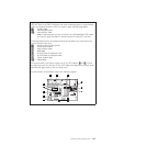
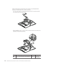
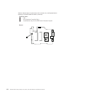
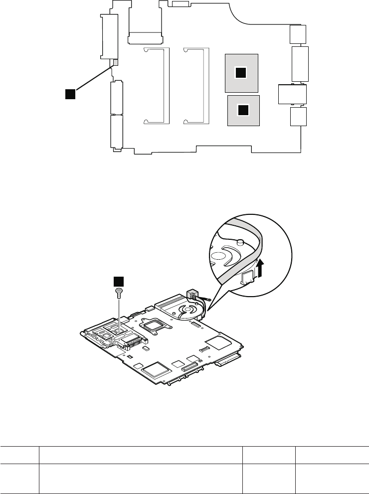
ThinkPad X201 and X201i:
a CPU
b PCH (Platform Controller Hub)
c Accelerometer chip for the HDD Active Protection System
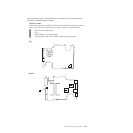
Bottom
a
b
c
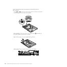
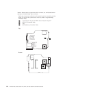
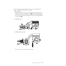
Note: The DC-in connector and the fan assembly are attached to the underside
of the system board.
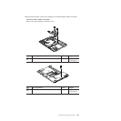
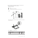
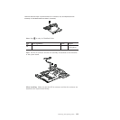
1
Note: Step 1 is only for ThinkPad X200.
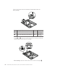
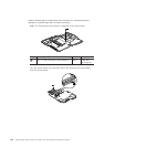
Step Screw (quantity) Color Torque
1 M2 × 3.5 mm, wafer-head, nylon-coated (1) Silver 0.181 Nm
(1.85 kgfcm)
Removing and replacing a FRU 127