


73
Lenovo IdeaPad Y460
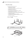
1210 Antenna assembly and LCD cover
For access, remove these FRUs in order:
• “1010 Battery pack” on page 35
• “1020 Dummy cards” on page 36
• “1030 Hard disk drive (HDD) slot cover and HDD” on page 37
• “1040 Optical drive” on page 39
• “1050 Thermal slot cover” on page 40
• “1070 Fan assembly and Heat Sink assembly” on page 42
• “1090 SIM card slot cover” on page 46
• “1100 PCI Express Mini Card for wireless LAN/WAN” on page 47
• “1120 Keyboard cover, power board and touch inductive panel” on page 50
• “1130 Keyboard” on page 53
• “1140 Keyboard bezel and speakers” on page 54
• “1150 System board and ExpressCard slot assembly” on page 60
• “1160 LCD unit” on page 64
• “1180 LCD front bezel” on page 68
• “1190 LCD panel, LCD cable and hinges” on page 69
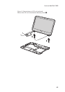
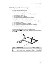
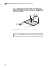
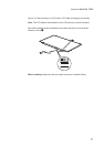
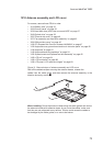
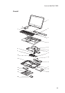
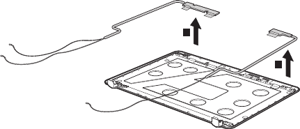
Figure 21. Removal steps of antenna assembly and LCD cover
Peel off the adhesive tapes securing the antenna boards, release the
cables from the cable guide, and then remove the antenna assembly in the
direction shown by arrows
1
.
1
1
When installing: Route the antenna cables along the cable guides and secure
the antenna boards with adhesive tapes. As you route the cables, make sure
that they are not subjected to any tension. Tension could cause the cables to
be damaged by the cable guides, or a wire to be broken.