


Lenovo Z710 Hardware Maintenance Manual
54
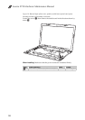
1120 LCD unit
For access, remove these FRUs in order:
• “1010 Battery pack” on page 34
• “1020 Dummy card (Optional)” on page 35
• “1030 Hard disk drive(HDD)/Memory/Mini PCI Express Card slot
compartment cover” on page 36
• “1040 Hard disk drive” on page 37
• “1050 Optical drive” on page 40
• “1060 DIMM” on page 41
• “1070 PCI Express Mini Card for wireless LAN/WAN” on page 42
• “1080 Keyboard” on page 44
• “1090 Fan assembly” on page 46
• “1110 System board” on page 50
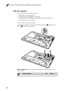
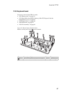
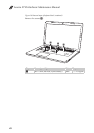
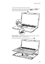
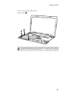
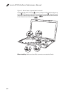
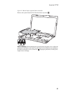
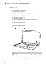
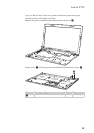
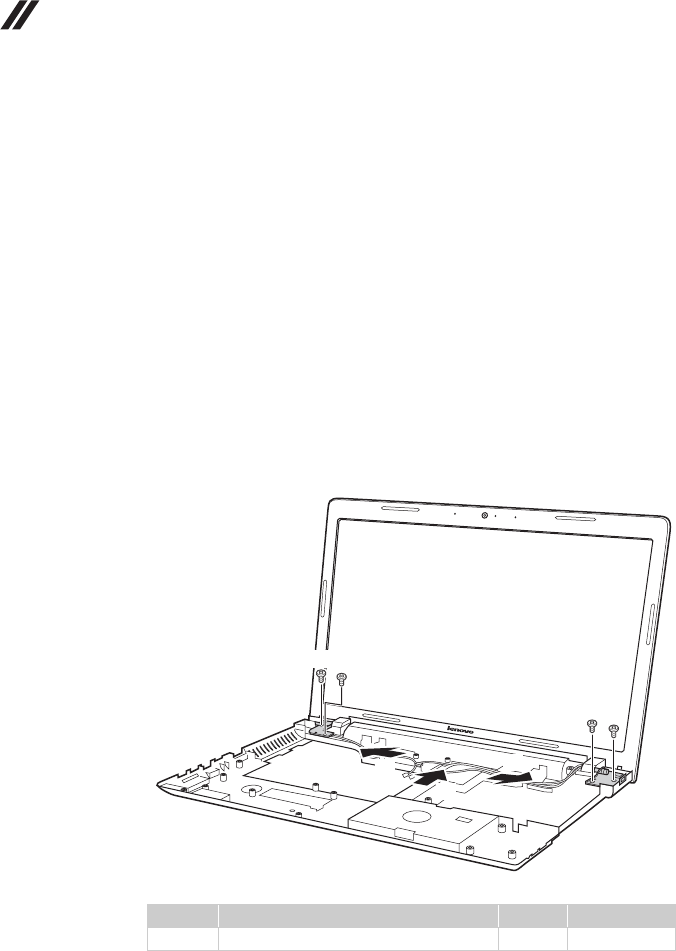
Figure 12. Removal steps of LCD unit
Release the antenna cables from the cable guides in the direction shown by
arrows . Remove four screws .
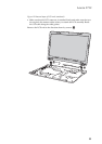
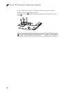
When installing:
• Route the antenna cables along the cable guides. As you route the cables,
make sure that they are not subjected to any tension. Tension could cause the
cables to be damaged by the cable guides, or a wire to be broken.
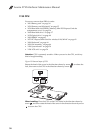
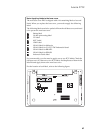
Step Screw (quantity) Color Torque
M2.5 × 5 mm, flat-head, nylok-coated (4) Black 1.5 ~ 2.0 kgfcm
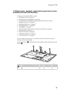
a b
b
b
a
a
a
b
b
b