


5. Module’s Letter and Number codes are set
correctly- that they match the codes set in the
Controller.
6. Confirm that the controller Is powered.
IMPORTANT:
If,
after checking Items 1 through 6,
the module
still
does not operate properly, the
fault may not
lie
with
the module itself.Follow
steps 7 and 8 to
identify
the source of the problem.
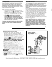
7. Set the controller to transmit address P1..Using a
Signal Strength Indicator, Cat. No. 6386, plugged
in at the location of the controller, Confirm that the
controller is transmitting a
minimum
reading of 2
volts of command
signal
at the HI-RANGE setting.
If the signal strength Is less than 2 volts, have
controller checked.
6. Check for adequate command signal at the
module location as follows:
a) Plug the Cat. No. 6385 Signal Test Transmitter
into a receptacle on the same circuit.
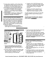
b) Using the Cat. No. 6386
Signal
Strength
Indicator at the module location, check the
command signal amplitude. Signal strength
must be 1
00mV
minlmum.
If there is less
than
DEC Components
are
for
RESIDENTIAL USE ONLY.
installation
for
any
other application, voids any warranty,
stated
or
implied.
1
1
OOmV
of signal present, it may be necessary
to couple both legs of the
120/240
volt power
service at the entrance panel using Cat. No.
6299 Signal Btfdge.
c) If the Yellow ERROR CONDITION indicator is
lit, there is electrical noise present on the AC
line which is interfering with proper module
operation. The source of the noise must be
identified and either filtered out or eliminated.
Consult the DEC Technical Manual and DEC
Troubleshooting Guide.
I’
I[
Home Automation Systems, Inc. (800) SMART-HOME
(949) 221-9200 http://smarthome.com