23
Using the 20/20 AD
20/20 AD User Guide
In 2-channel mode, when the LINK switch is off, each of the two channels is
compressed independently. When the LINK switch is on, the louder of the two
channels sets the amount of compression. This serves the same function as
“stereo link” in analog compressors. When you are recording a stereo signal and
want to maintain the stereo image, LINK should be on. However, if you have the
compressor set up to protect against short overloads, or if you have the release
time set to 0, keeping LINK off will probably sound better. When recording two
mono signals, LINK should be off.
In 4-channel mode, when the LINK switch is off, channels 1 and 2 and channels
3 and 4 are linked in stereo pairs. When the link switch is on, all four channels
are linked. (There is no way to compress four mono signals.)
When the DISPLAY switch is on, the level meters indicate the amount of
compressor gain reduction
in each channel. This shows the amount that gain (in
dB) which is being reduced as the input level exceeds the threshold.
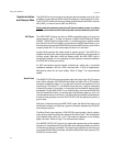
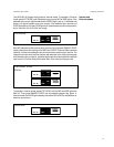
LINK
DISPLAY
The 20/20 AD provides two sets of digital audio output connectors with three
connectors in each set. In four-channel mode, the first set contains digitized CH1
and CH2, the second set contains CH3 and CH4. In two-channel mode, both
sets contain identical copies of digitized CH1 and CH2. The unused set may be
used to drive a backup recorder or to synchronize another 20/20 AD.
Each set of digital outputs contains three connectors: an XLR connector which
transmits AES3 digital audio, an RCA connector which transmits an S/PDIF-
compatible digital audio signal, and a TOSLINK-compatible optical transmitter.
All outputs are always active. The front panel FORMAT switch selects
between AES and S/PDIF-compatible Channel Status bits, but it doesn’t enable
or disable the actual transmitters. Make sure that the FORMAT setting is set for
AES when using the XLR connector and S/PDIF when using the RCA or optical
connectors.
Pin 1 of the AES outputs is connected to system ground through jumpers W26
and W27. If the shield is connected to ground at the receiver end, these jumpers
should be opened. Note that, because of the transformer or optical isolation, it
is not necessary to connect the ground between the 20/20 AD and the equipment
receiving the digital audio data, regardless of which output type you choose.
As mentioned above, only appropriate high-frequency cables should be used for
digital audio. Refer to Page 7 for recommended cables.
Digital Audio Outputs


