


Owner’s Manual 7
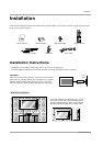
Introduction
Controls
Controls
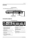
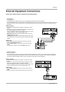
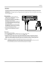
Connection Options
Connection Options
RS-232C INPUT
(CONTROL/SERVICE)
VIDEO
INPUT
YP
B
P
R
(MONO)
R
AUDIO
L
R
AUDIO
L
S-VIDEO
AC INPUT
AUDIO INPUT
AUDIO INPUT
AUDIO INPUT
R
( )
( )
( )
( )
L
EXTERNAL SPEAKER
COMPONENT INPUT
DVI INPUT
RGB INPUT
RGB OUTPUT
REMOTE CONTROL
5
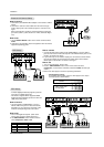
1. RS-232C INPUT (CONTROL/SERVICE) PORT
Connect to the RS-232C port on a PC.
2. DVI (Digital Visual Interface) INPUT/
RGB INPUT/AUDIO INPUT JACKS
Connect the monitor output connector from a PC to the
appropriate input port.
3. RGB OUTPUT PORT
You can watch the RGB signal on another monitor, connect
RGB OUTPUT to another monitor’s PC input port.
4. REMOTE CONTROL
Connect your wired remote control to the remote control
port on the Monitor.
5. EXTERNAL SPEAKER (8 ohm output)
Connect to optional external speaker(s).
* For further information, refer to ‘Speaker & Speaker
Stand’ manual.
6. COMPONENT INPUT/AUDIO INPUT JACKS
Connect a component video/audio device to these jacks.
7. S-VIDEO INPUTS
Connect S-Video out from an S-VIDEO VCR or other S-
Video device to the S-VIDEO input.
AUDIO/VIDEO INPUT JACKS
Connect audio/video out from external equipment to these
jacks.
8. POWER CORD SOCKET
This Monitor operates on an AC power. The voltage is indi-
cated on the Specifications page. Never attempt to operate
the Monitor on DC power.
Back Connection Panel
Back Connection Panel
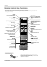
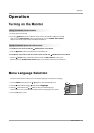
VOLUME
INPUT
SELECT
ON/OFF
Main Power Button
INPUT SELECT Button
VOLUME (
F,G) Buttons
Remote Control Sensor
Power Standby Indicator
Illuminates red in standby
mode. Illuminates green when
the Monitor is turned on.
Sub Power Button
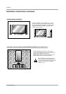
Front Panel Controls
Front Panel Controls
1 3 42 7
8
6
- This is a simplified representation of a typical front panel.
The Front Panel Controls shown here may be somewhat different from your monitor.