


32 Operation
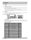
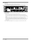
4.2.2 Rear Panel
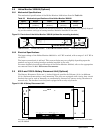
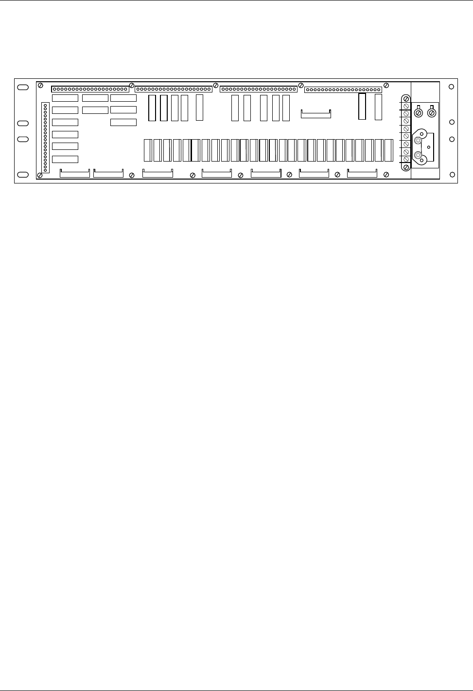
The rear panel of the Conventional Controller is provided with the connection interface features
shown in
Figure 30
and described in the following subsections.
Figure 29 Terminal blocks and connectors layout at the rear of the Conventional Controller
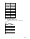
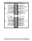
Terminal blocks
Six terminal blocks to interface with external wiring as follows:
• TB1: various alarm outputs to the office alarm circuits and the cabinet alarm lamp
• TB2: various alarm outputs to the office alarm circuits, and remote equalize signal input
• TB3: various alarm outputs to the office alarm circuits, and charge and discharge fuse alarm
inputs
• TB4: various alarm outputs to the office alarm circuits, and LVD control and alarm
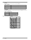
• TB5: various alarm outputs to the office alarm circuits, remote TR signal input, -48 V supply
to cabinet alarm lamp and various small loads, and AUX 1 and AUX 2 alarms inputs
• TB6: -48 V supply to office alarm circuits if required, VR+ and VR- inputs, and -48 V and
ground inputs
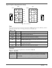
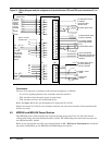
Refer to
Figure 30
and
Figure 31
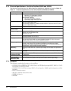
for the pin assignment of terminal blocks TB1 to TB6.
TB2
J7 J6
TB1
J8
TB6
TB5
P1P9 P7 P5
J1
J2
P3P15 P13 P11
J3
TB4
P25 P23 P21 P19 P17
J5
J4
TB3
1
8
P2P10 P8 P6 P4P16 P14 P12P22 P20 P18P24P26