Series 300 Load Bus Synchronization 2
SECTION 2 THEORY OF OPERATION
2.1 GENERAL DESCRIPTION
The Liebert Series 300 Load Bus Sync (LBS) option works by monitoring the sync reference signals of
two UPS modules, each equipped with a specially designed interface. The LBS remains dormant until
the outputs of the UPS modules drift more than a predetermined amount out of sync. In the event of an
out of sync condition, the LBS becomes active and brings the output of both UPS modules back in
sync, and then resumes the dormant state.
2.2 LOAD BUS SYNC CONTROLLER
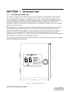
The Series 300 LBS controller fits into a compact 20x24 inch enclosure. The front panel controls are
simple and fault tolerant. They enable the operator to do the following:
A. Select whether the controller will function automatically or be “Off.”
B. Select which UPS, (System 1 or System 2) will become the Designated Master System
(DMS). The other UPS module will become the Designated Slave System (DSS).
2.3 SERIES 300 LBS MODULE INTERFACE
In order for the LBS controller to send and receive signals from the Series 300 modules, each module
must have the proper interface installed. The Series 300 interface consists of two main components as
follows:
A. The LBS Interface Panel
B. The LBS Adapter PWA
The LBS Interface Panel has many configurations to accommodate the many input and output voltages
available on the Series 300 UPS. The LBS Adapter PWA has only one configuration, which is used with
all Series 300 LBS installations.
The LBS Interface Panel performs the following functions:
A. Receives and scales sync signals from the LBS Controller.
B. Receives signals from the LBS Controller to determine whether to use internal sync or
sync to the other UPS module.
C. Receives static switch disable signals from the LBS Controller.
D. Provides the LBS Controller with bypass voltage signals, output voltage signals and
bypass available signals.
E. Provides the LBS Controller with 120 VAC control power.
The LBS Adapter PWA performs the following functions:
A. Receives and shapes sync signals for the LBS Interface Panel and routes the sync signal
to the processor board.
B. Selects the sync source, either internal or from the other UPS based on signals that
originate with the LBS Controller and passed on through the LBS Interface Panel.
C. Disables the static switch on the slave UPS when the slave UPS is acquiring sync with the
master UPS.
DISCONTINUED
PRODUCT


