


Surge Suppression Systems
Installation, Operation and Maintenance Manual 13 Liebert TVSS Units SL-22085 Rev 2, 11/2006
Installation Instructions
All electrical connections shall be installed by a qualifi ed (licensed) electrician. All wiring must comply with the National Electrical
Code (NEC) and applicable local codes.
National Electrical Code (NEC) Considerations
The National Electrical Code Article 240-21 details specifi c tap rules that should be considered before installation.
NEC 240.21 Location in Circuit. Over current protection shall be provided in each ungrounded circuit conductor and shall
be located at the point where the conductors receive their supply except as specifi ed in 240.21(A) through (G). No conductor
supplied under the provisions of 240.21(A) through (G) shall supply another conductor under those provisions, except through
an over current protective device meeting the requirements of 240.4.
(A) Branch-Circuit Conductors. Branch-circuit tap conductors meeting the requirements specifi ed in 210.19 shall be
permitted to have over current protection located as specifi ed in that section.
(B) Feeder Taps. Conductors shall be permitted to be tapped, without over current protection at the tap, to a feeder as
specifi ed in 240.21(B)(1) through (5).
(1) Taps Not Over 3 m (10 ft) Long. Where the length of the tap conductors does not exceed 3 m (10 ft) and the tap
conductors comply with all of the following:
(1) The Ampacity of the tap conductors (25 Amps in our case) is
a. Not less than the combined computed loads on the circuits supplied by the tap conductors, and
b. Not less than the rating of the device supplied by the tap conductors or not less than the rating of the over
current protective device at the termination of the tap conductors.
(2) The tap conductors do not extend beyond the switchboard, panelboard, disconnecting means, or control devices
they supply.
(3) Except at the point of connection to the feeder, the tap conductors are enclosed in a raceway, which shall extend
from the tap to the enclosure of an enclosed switchboard, panelboard, or control devices, or to the back of an
open switchboard.
(4) For fi eld installations where the tap conductors leave the enclosure or vault in which the tap is made, the rating
of the over current device on the line side of the tap conductors shall not exceed 10 times the Ampacity of the
tap conductor.
(2) Taps Not Over 7.5 m (25 ft) Long. Where the length of the tap conductors does not exceed 7.5 m (25 ft) and the tap
conductors comply with all of the following:
(1) The Ampacity of the tap conductors is not less than one-third of the rating of the over current device protecting the
feeder conductors (75 Amp maximum in our case).
(2) The tap conductors terminate in a single circuit breaker or a single set of fuses that will limit the load to the
Ampacity of the tap conductors. This device shall be permitted to supply any number of additional over current
devices on its load side.
(3) The tap conductors are suitably protected from physical damage or are enclosed in a raceway.
(3) Taps Supplying a Transformer. Not Applicable
(4) Taps Over 7.5 m (25 ft) Long. Not Applicable
(5) Outside Taps of Unlimited Length. Not Applicable
Flexible liquid tight non-metallic conduit in lengths greater than six feet must be installed in accordance with NEC 351-27.
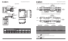
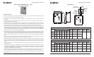
Liebert AccuGuide Series — Type ACG
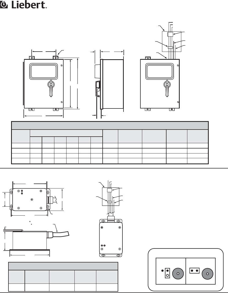
SPD Interconnect Assembly
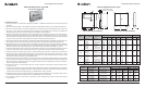
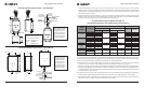
AccuVar Series
Weight
(lbs)
Suggested
Breaker Size
Suggested
Wire Size
(AWG)
Allowable
Breaker
Range
Allowable
Wire Range
8 30A #10 15A-30A #14-#10
Hybrid Advantage
Unit
Dimensions (Inches)
Weight
(lbs)
Suggested
Breaker Size
Suggested
Wire Size
(AWG)
Allowable
Breaker
Range
Allowable
Wire Range
A B C D E F
111
222
333
444
16
20
24
24
9
9
9
9
21.25
21.25
25.25
31.25
10
14
18
18
0.44
0.44
0.44
0.44
56
82
115
153
60 A
80 A
80 A
100 A
#6
#4
#4
#2
15A – 150A
15A – 175A
15A – 175A
15A – 175A
#14 – 1/O
#14 – 2/O
#14 – 2/O
#14 – 2/O
20
24
24
30
Installation, Operation and Maintenance Manual 16 Liebert TVSS Units SL-22085 Rev 2, 11/2006
Surge Suppression Systems
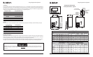
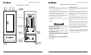
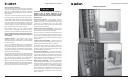
Hybrid Advantage Series — Type H
AccuVar Series – Type ACV & AII
E
F
(4X)
B
A
D
C
1.840
Max.
2.625
Max.
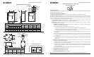
Service Panel for
Loads to be Protected
Phase L1/A
Phase L2/B
Phase L3/C
Disconnect/Main
Breaker for
Panel
Neutral Buss
Ground Buss
Dedicated
Disconnect
(Optional)
Recommended Wire
Entrance
6.875
7.375
0.212
8.125
3.088
4.125
4.750
Slots Will Accept
8-32 Screws
1/2 Flexible Conduit
9.00 Minimum
Trim to Fit
Service Panel for
Loads to be Protected
/
Phase L2/B
Phase L3/C
Disconnect/Main
Breaker for
Panel
Neutral Buss
Ground Buss
Dedicated
Disconnect
(Optional)
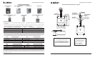
STATUS
STATUS
*Factory Setting
Jumper located next to alarm
*Alarm ENABLED Alarm DISABLED
Audible Alarm — AccuVar Series
Jumper Jumper AlarmAlarm
Alarm Enable/Disable Feature
Liebert Interceptor II Printer S15 15 12/29/06 1:38:00 PM