


Installation Drawings
12
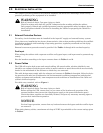
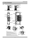
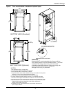
Figure 4 Bottom cable entry routing and installation order
SIDE VIEW
FAULT BRACE
OUTPUT
FAULT BRACE
RECTIFIER INPUT
FAULT BRACE
BYPASS INPUT
BYPASS NEUTRAL
DC (POSITIVE)
DC (NEGATIVE)
GROUND (TOP ENTRY)
BYPASS INPUT
RECTIFIER
INPUT
OUTPUT
OUTPUT NEUTRAL
GROUND (BOTTOM ENTRY)
FRONT VIEW
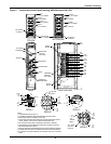
Recommended order of installation for cables:
1.) Output Neutral
2.) Output Power (Phases A-B-C)
3.) Rectifier Input Power (Phases A-B-C)
4.) Bypass Input Power (Phases A-B-C)
5.) Bypass Neutral
6.) DC Power
7.) Ground
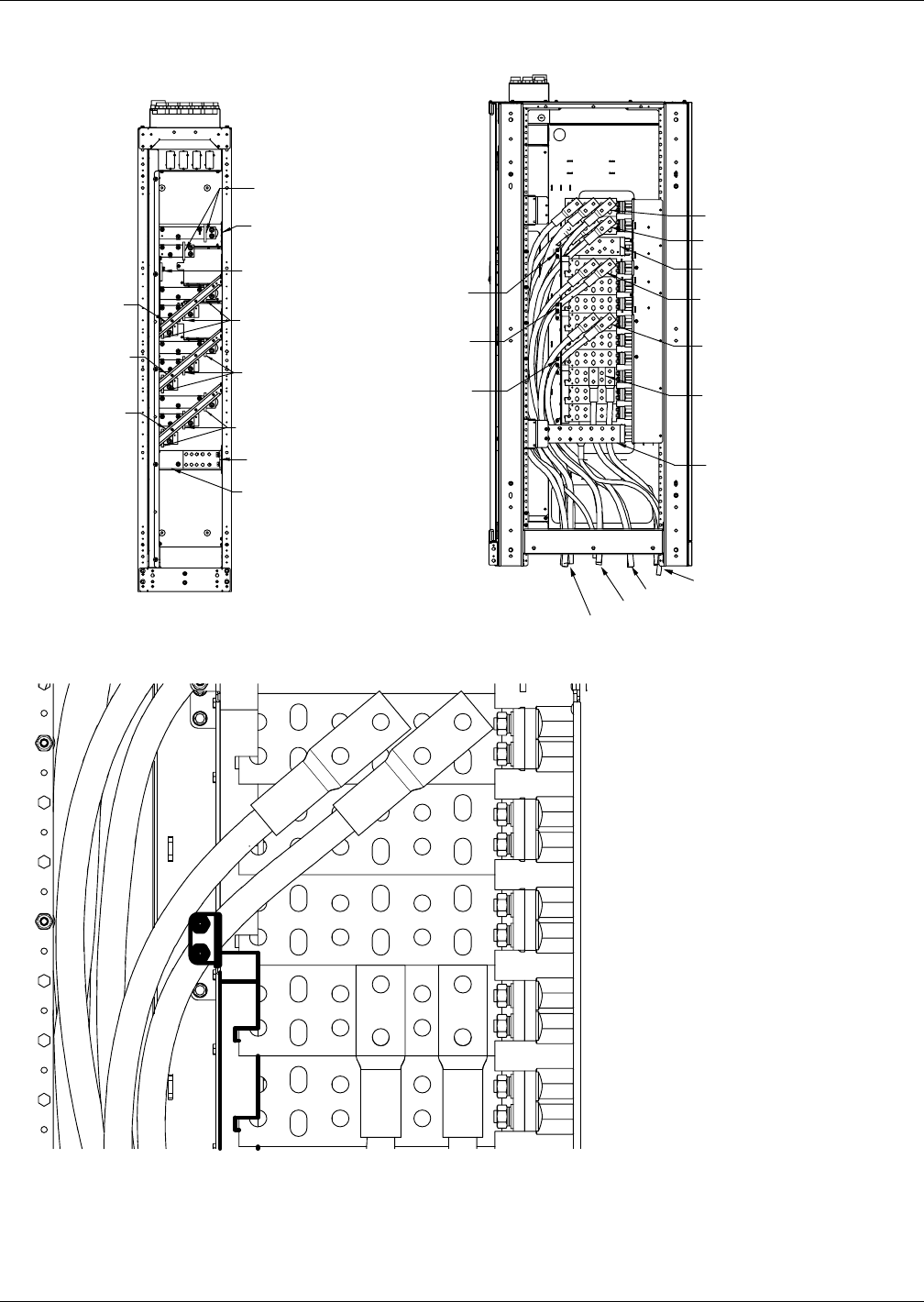
OUTPUT (PHASE C)
RECTIFIER INPUT
(PHASE C)
BYPASS INPUT
(PHASE C)
BYPASS NEUTRAL
OUTPUT NEUTRAL
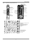
FAULT BRACE
BYPASS INPUT
FAULT BRACE
RECTIFIER INPUT
FAULT BRACE
OUTPUT
DC (POSITIVE)
DC (NEGATIVE)
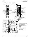
DC CONDUIT
BYPASS CONDUIT
INPUT CONDUIT
OUTPUT CONDUIT
The cables must be routed
around the fault braces. This is
to prevent the cables from
coming in contact with
other busbars.