


Installation, Operation and Maintenance Manual 10 Liebert TVSS Units SL-22085 Rev 2, 11/2006
Surge Suppression Systems
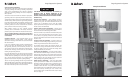
Liebert Active Tracking Filter Series — Type F
Surge Protective Device (SPD)
Installation Instructions
1. Ampacity: The fi lter’s maximum continuous current (Ampere) rating must be greater than or equal to the protected load’s full
load amps or overcurrent protection (Circuit Breaker) rating.
2. Insure that all power is removed before beginning installation. A qualifi ed licensed electrician shall install all electrical
connections.
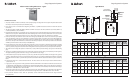
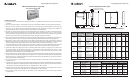
3. The SPD is provided in a NEMA 3R, NEMA 4, NEMA 4X or NEMA 12 enclosure. The SPD is suitable for use in indoor (NEMA 12)
or outdoor (NEMA 3R, 4, 4X) installations.
4. Determine where the SPD is to be mounted. Punch or cut proper hole size in the side of the SPD closest to the knockout to be
utilized in the service panel. Wall Mounted Units: Drill mounting holes in wall at location picked for SPD next to service panel
using mounting dimension from the tables on page 17. Mount surge suppressor using 3/8-16 hardware or equivalent.
5. Units up to 225 amps are suitable for short circuit current ratings up to 25,000 amps. For short circuit currents up to 50,000
amps, Class RK5 fuses sized up to 125% of the fi lter’s continuous current rating are required. Units rated at 400 to 800 amps
are suitable for available symmetrical short circuit currents up to 50,000 amps. For short circuit currents up to 100,000 amps,
Class L Fuses sized up to 125% of the fi lter’s continuous current rating are required. Units 1200 amps and above are suitable for
available symmetrical short circuit currents up to 200,000 amps.
6. For best performance, keep input and output wiring separated as much as practical to eliminate input-to-output coupling
of noise and transients. Do not route input and output wiring in the same raceway. If practical, terminate input and output
raceways (conduits) at opposite ends of the active tracking fi lter enclosure (input near the top and output near the bottom).
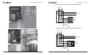
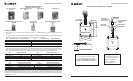
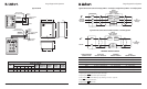
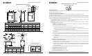
7. The Liebert Active Tracking Filter System is wired in-line (in series) with the protected load(s). See Figures on the following
page.
8. Terminals are provided inside the Liebert Active Tracking Filter System for the line (phase), neutral (if used), transient ground,
and equipment safety ground connections. See page 11 for terminal wire size ranges.
9. Connect black wires (line or phase) marked L1/A, L2/B or L3/C, the white wire (neutral) marked N, and the green wire (ground)
marked G, of the SPD using the wire range listed in the table on page 12 in accordance with the National Electric Code (NEC)
Article 285 and all local codes. To yield the best performance of the SPD within the electrical distribution system, avoid sharp
bends.
10. Connection to the Form ‘C’ contacts shall be with #18 – 22 AWG. Contacts are rated 5 amps at 250 VAC maximum with a
power factor of 1.0.
11. Apply power. The surge protector is fully operational when the GREEN LEDs on the modules and the front door of enclosure
are illuminated. If the GREEN LEDs are extinguished or the RED LED is illuminated, check to ensure that power is applied to
the SPD. If an abnormal indication is present, remove power to the SPD and contact Liebert/Emerson Network Power Surge
Protection at 1-800-288-6169 or 1-607-724-2484.
12. Periodically monitor the status of the LEDs. Reduced protection exists if the GREEN LEDs are extinguished or the RED LED is
illuminated. Please contact Liebert/Emerson Network Power Surge Protection at 1-800-288-6169 or 1-607-724-2484.
13. The protection modules in these SPDs are replaceable, contact Liebert/Emerson Network Power Surge Protection
for replacement.
Surge Suppression Systems
Installation, Operation and Maintenance Manual 19 Liebert TVSS Units SL-22085 Rev 2, 11/2006
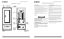
Type LM Series
E
F
(4X)
B
A
D
C
1.840
Max.
Service Panel for
Loads to be Protected
Phase L1/A
Phase L2/B
Phase L3/C
Disconnect/Main
Breaker for
Panel
Neutral Buss
Ground Buss
Dedicated
Disconnect
(Optional)
Recommended Wire
Entrance
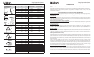
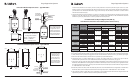
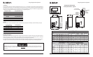
LM Series
Unit
Dimensions (Inches)
Weight
(lbs)
Suggested
Breaker Size
Suggested
Wire Size
(AWG)
Allowable
Breaker
Range
Allowable
Wire Range
A B C D E F
LM060
LM080
LM100
LM125
LM150
LM200
LM225
LM250
14
14
16
8
8
9
16.75
16.75
21.25
12
12
10
0.31
0.31
0.44
32
41
56
40 A
40 A
100 A
#8
#8
#2
15A –100A
#14 – #2
16
16
20
LM Series, with Rotary Disconnect
Unit
Dimensions (Inches)
Weight
(lbs)
Suggested
Breaker Size
Suggested
Wire Size
(AWG)
Allowable
Breaker
Range
Allowable
Wire Range
A B C D E F
LM060
LM080
LM100
LM125
LM150
LM200
LM225
LM250
14
14
16
8
8
9
16.75
16.75
21.25
12
12
10
0.31
0.31
0.44
32
41
56
40 A
40 A
100 A
#8
#8
#2
15A –150A #14 – 1/O
16
16
20
15A –175A
15A –175A
#14 – 2/O
#14 – 2/O
Liebert Interceptor II Printer S12 12 12/29/06 1:37:59 PM