Communications
21
10.0 COMMUNICATIONS
10.1 Communications Interface Port
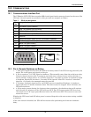
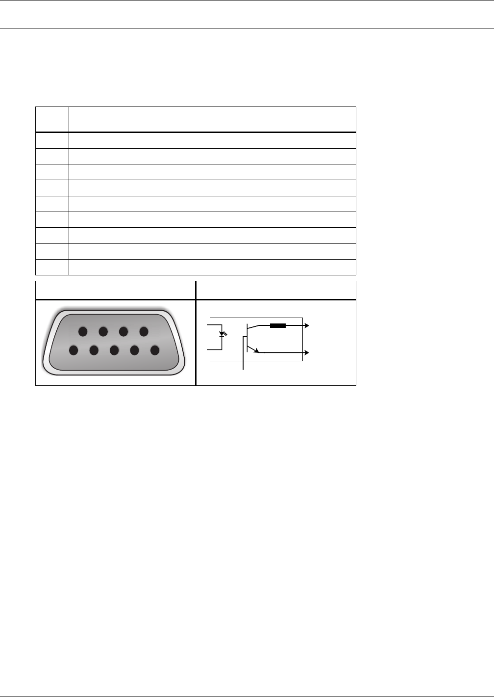
The UPStation GXT2 UPS has a standard DB-9 serial port female connector located on the rear of the
UPS unit. Several signals are provided on this port and are assigned as follows:
10.2 Pin 4 - Remote Shutdown on Battery
1. 1. This pin is functional only when the UPS is in battery mode. If the UPS is being powered by the
mains, Pin 4 will ignore any signal on this pin.
2. 2. Pin 4 requires a 5-12 VDC signal to shutdown. This normally comes form the serial port using
Liebert's contact closure cable. It cannot be used with just a contact closure unless the relay is
used to switch a voltage source. A 5-12 VDC signal for 1.5 seconds or greater is required to signal
a shutdown. Signals for less than 1.5 seconds will be ignored. After Pin 4 receives a shutdown
signal for 1.5 seconds, the command cannot be canceled.
3. 3. A battery shutdown signal on Pin 4 will NOT cause an immediate Shutdown. A shutdown
signal will start a 2-minute shutdown timer. The timer cannot be stopped. After 2 minutes, the
UPS will shut down.
4. 4. If the mains returns during the 2-minute timer countdown, the shutdown timer will continue
until the end of 2 minutes and the UPS will turn OFF. The UPS must remain OFF for at least
10 seconds even if AC input power Returns before the UPS turns OFF. This serves to reset and
restart the server.
Whether the UPS turns back ON when power is restored depends on the auto-restart setting: enabled
or disabled.
If the auto-restart is disabled, the UPS will not restart after performing the 2-minute shutdown
delay.
Table 2 DB-9 pin assignment
DB-9
Pin
Assignment Description
1 Low Battery (open collector)
2 UPS TxD (typically RS-232 levels)
3 UPS RxD (typically RS-232 levels)
4 Remote Shutdown (5-12VDC, 10-24mA max; battery operation)
5 Common
6 Remote Shutdown (short to pin 5); all modes of operation
7 Low Battery (open emitter)
8 Mains Fail (open emitter)
9 Mains Fail (open collector)
Pin Assignment Collector to Emitter*
* Maximum voltage and current on pins 1, 7, 7 and 9 are 60VDC and 10.0 mA
54321
6789
(-)
(+)
330 Ohms
Open
Collecto
r
Open
Emitter


