4
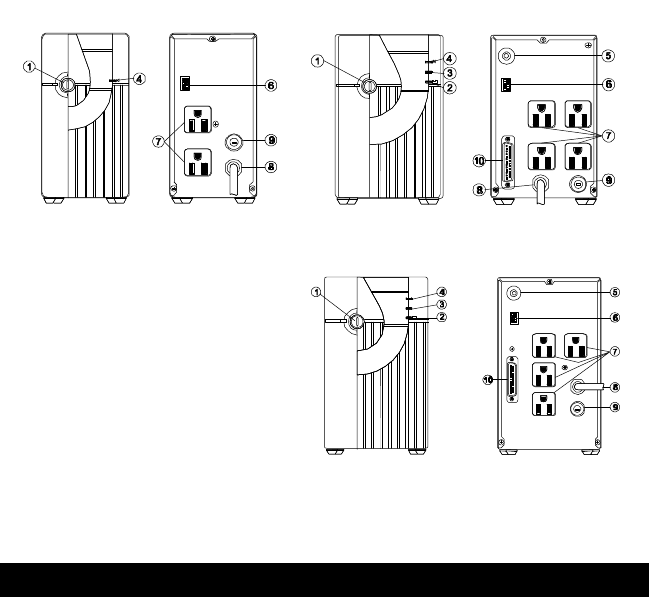
1. ON/OFF Button
2. Battery Light (400/600 Only)
3. Check Light (400/600 Only)
4. AC Light
5. Battery Test Button / Alarm Silence
(400/600 Only)
6. Option Switches
7. Output Receptacles
8. Power Cord Input
9. Circuit Breaker
10. Communications Port (400/600 Only)
ATTENTION: Please refer to these drawings when reading this
manual. This manual references the various parts of your UPS by
number.
GENERAL INSTALLATION
1. Unpack the unit and check the contents. There should be one UPS with
power cord (8) and one User’s Manual.
2. Check the items for damage. If any appear faulty or damaged, contact your
dealer immediately. Store the packaging in a safe place for possible future
shipment of UPS.
3. Place the UPS on a sturdy, dry surface in a well ventilated area away from
direct heat sources. Leave at least 4 inch (100 cm) clearance all around the
UPS to provide adequate ventilation.
4. Plug in the UPS and turn the UPS control switch (1) to ON.
5. Plugging in the UPS charges the batteries. Charge the UPS batteries for 12
hours before connecting the load equipment.
6. After charging the UPS, shut down your computer and unplug it. Plug the
computer equipment into the UPS AC outputs (7).
7. When all equipment is plugged in, the UPS is ready for normal operation.
250 VA / 115 V
400 VA / 115 V
600 VA / 115 V


