


Controls and Indicators
15
4.1 Control Buttons
4.1.1 On/Alarm Silence/Manual Self-Diagnostic Test
This button controls output power to connected load(s). It has three functions:
•On
•Alarm Silence
• Manual Self-Diagnostic Test
ON—Start the UPS by pressing this button for more than 3 seconds, then releasing the button (an
alarm will sound briefly). If the ON button is pressed and utility is outside input parameters, the UPS
will start on battery (dark start).
Alarm Silence—Silence a battery mode audible alarm by pressing this button for longer than one
second, then releasing it.
Manual Self-Diagnostic Test—To initiate a Manual Self-Diagnostic, press this button for at least
three (3) seconds while operating from utility power. UPS will switch to Battery Mode to detect bat-
tery voltage and whether the UPS is operating normally.
If LED indicates the battery is weak: Allow the UPS to recharge the batteries for 8 hours.
Retest the battery after recharge.
If LED still indicate battery weak after the battery has been retested, contact your local
dealer, Emerson representative or Liebert Applications.
If LED indicates a Battery Fault: Contact your local dealer, Emerson representative or Liebert
Applications.
If LED indicates UPS Fault: Remove the load, retest the self diagnostic test, if LED indicated
UPS Fault, Contact your local dealer, Emerson representative or Liebert Applications.
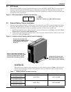
4.1.2 Off Button
When the UPS is operating in either Normal Mode or Battery Mode, pressing the Off button for more
than three seconds will shut down the UPS.
4.2 Status Indicators
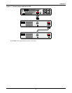
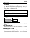
4.2.1 Status Change Button
The Status Change Button determines the information displayed by the five LEDs on the front panel.
The default information shown by the LEDs is the load level on the UPS. Pressing the Status Change
Button while the UPS is On prompts the LED display to show battery capacity for 5 seconds. This
function assists in assessing the meaning of status indicators as described in 4.2.4 - UPS Status
Indicators. See Figure 16 and Table 2 for the Status Change Button’s location.
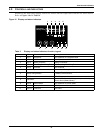
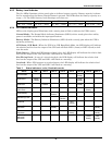
4.2.2 Load Level Indicator
The five LEDs at the top of the front panel illuminate with a steady glow to indicate the load level on
the output of the UPS. The LEDs show the load level as a range, ± 5%. The LEDs’ load level meanings
and colors are:
NOTE
Refer to Figure 16 and Table 2 for details about the LEDs’ meaning.
LED 1 LED 2 LED 3 LED 4 LED 5
10 - 24% — Green 25 - 49% — Green 50 - 74% — Yellow 75 - 99% — Yellow 100% or greater — Red