


User Manual 2
Features
• Remote access power strip with remote management function via RS-232 port
• One or all outlets can be switched via RS-232 commands, terminal program, script or modem
• Power switch status remains during power loss and after power has returned
• Up to 32 power strips can be cascaded in an integrated RS-485 bus
Packing List (8 Port Model in brackets)
• 1 x Power Strip + User Manuals + CD
• 4(8) x OUTPUT mains cables, IEC-320 male – IEC-320 female, approx. 1.8m
• 1(2) x INPUT mains cables, INPUT Schuko male – IEC-320 female, approx. 1.8m
• 1x Serial RS-232 cable, RJ-10 to D9-female, approx. 2m
Installation
The 4 port power strip is rack mountable in a 19”, 1U bay. The 8 port model can be mounted vertically. The
brackets can be adjusted to almost any position for maximum flexibility when installing.
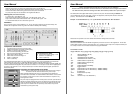
Components and Elements
1 Programming block (covered by protective plate)
2 Address DIP switches (covered by protective plate)
3 Serial RJ-10 socket for RS-232 access
4 Bus IN and OUT (cascading), RJ-45 socket
5 Bus IN and OUT (cascading), RJ-45 socket
6 Status LED for INPUT voltage 1
7 Status LEDs for OUTPUT voltage 1-4
8 Outlets 1-4 (230V AC)
9 INPUT 1 (230V AC)
The supplied RS-232 cable (D9f to RJ-10) is used to connect the power strip to the RS-232 port of the devices
which manage the power strip (i.e. LINDY Rack Monitoring System, IP Access Switch Plus, etc.)
The power strip is powered using
INPUT 1 (9)
. The power status is monitored by the
INPUT STATUS LED
(6). The
OUTPUT STATUS LED’s
(7) show the power status of
OUTLETs 1-4
. For the 8 port model,
INPUT 2
(12) supplies
the power to the
OUTLETs 2.1-2.4
- this provides the option to switch redundant power supplies, powered from
different AC phases.
Cascading of multiple RS-232 Power Strips
Please make sure that there is NO connection to the mains when changes
are made to the DIP switches! Detach ALL power strips!
When cascading multiple power strips over large distances the RS-485 bus
termination has to be enabled. To enable termination DIP switches 7 and 8 (under
the protective covers) have to be set to ON. This termination is required for any
bus lengths above 100m.
The power strips are equipped with an internal protocol converter (from RS-232 to
RS-485) to cascade multiple power strips. The cables used to cascade the power
strips are standard RJ-45 patch cables. Just connect the
BUS OUT
from the first
power strip to the
BUS IN
of the next power strip and continue until you have
cascaded all (up to 32) power strips.
8 port mode
l
only
(
No. 3245
3
)
10 Status LED for INPUT voltage 2.1-2.4
11 Outlets 2.1-2.4 (230V AC)
12 INPUT 2 (230V AC)
User Manual 3
Every cascaded power strip has to be set to its own address!
Please make sure that there is NO connection to the mains when changes are made to
the DIP switches (Address settings and Bus termination)! Detach ALL power strips!
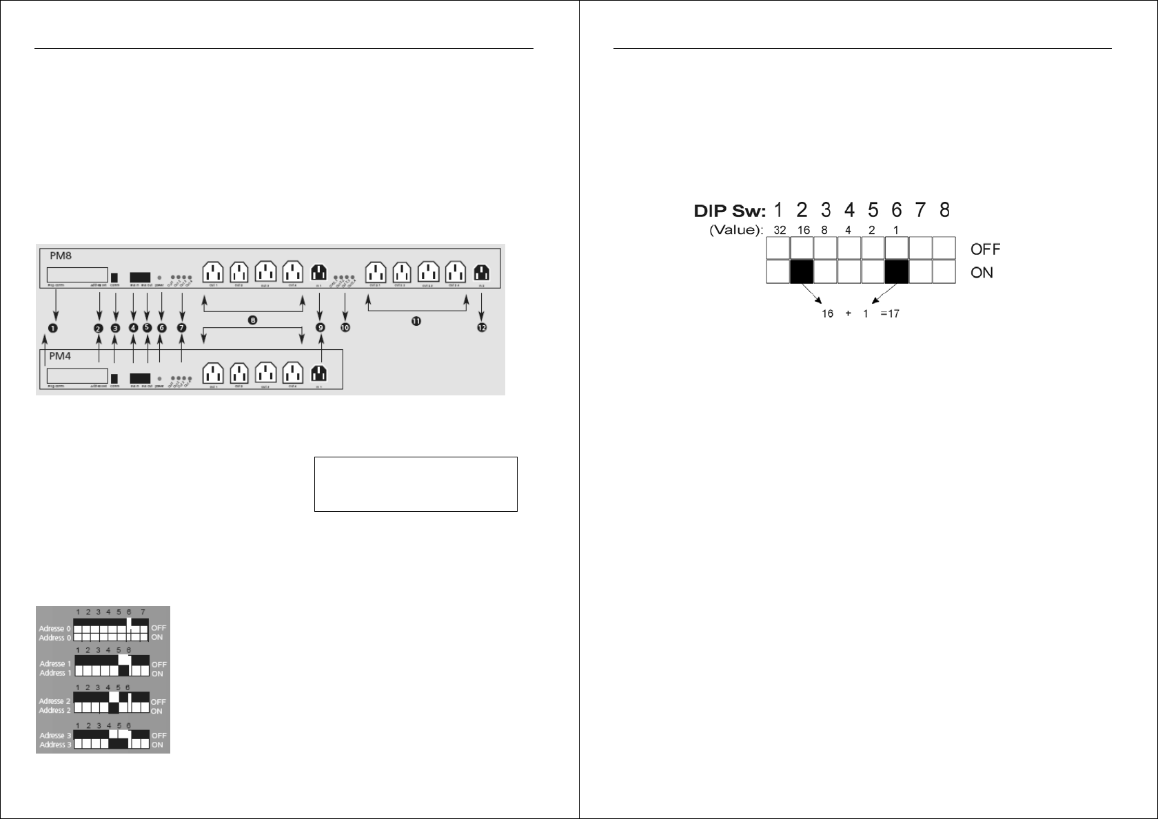
The Address DIP switch (2) is hidden behind a protective cover plate. The default setting is Address = 0.
Up to 64 addresses can be set. DIP switch 1 refers to the highest bit (value=32), DIP switch 6 to the lowest
(value=1). All switches OFF means Address = 0.
Example : To set the address to 17( = 16 + 1), DIP switch 2 and 6 have to be "ON”. See below –
Please close the protective cover after address and termination settings have been made.
RS-232 Management
Detailed documentation about the RS-232 management protocol can be found on the supplied CD. The CD also
contains DOS programs and other tools which allow you to access the power strips from a computers RS-232 port.
For example, here are the commands available in the program PMODULE:
PowerModule V0.60
usage: PModule -dx [-i][-s[x]][-onx][-offx][-a[d]x][-tox][-f][-tx.xx][-v][-comx]
-d device address x (0..31)
-i read device type
-s read status from all outlets
-sx read status from outlet x (1..8)
-onx switch outlet x on (9 for all)
-offx switch outlet x off (9 for all)
-ax switch all binary
-adx switch all binary with delay
-tox toggle outlet x
-ponx t pulse outlet x on off with time t (1..16383 x 100ms)
-poffx t pulse outlet x off on with time t (1..16383 x 100ms)
-f find devices
-tx.xx timeout factor (-t1.25)
-v verbose
-comx use com x (1 or 2, default is 1)