5
4
The VE-120 package contains:
* VE-120L x 1
* VE-120R x 1
* VGA Cable x 1
* Category 5 STP Cable (optional)
* Power Adapter x 2
* User's Manual x 1
Read this guide thoroughly and follow the installation and operation
procedures carefully to prevent any damage to the units and/or any of the
devices they connect to.
©Copyright 1999 ATEN® International Co., Ltd.
Manual Part NO. PAPE -1141-100
All brand names and trademarks are the registered property of their respective owners.
USER'S MANUAL
VE-120
VE-120
6.Slide the Range Switch to the Long position if the
Remote Unit location is a long distance away; slide
the switch to the Short position if the Remote
Unit location is a short distance away
7.Plug the other end of the Category 5 twisted pair
cable into the Remote Unit's Remote I/O port*
Note: See the Cable Length table in the Appendix
for typical resolution/refresh rate/distance
ratios.
8.Plug the remote monitor's VGA cable into the
Remote Unit's Monitor port
9.Plug the second power adapter (supplied with this
package) into an AC source; plug the adapter's
power cable into the Remote Unit's AC 9V Power
Jack
10.Power On the computer and monitors
* If Category 5 cable was supplied as part of this
package, it is quite short and primarily intended for
testing purposes. For practical use, you will
probably want to purchase a longer cable.
Technical Details
Troubleshooting
Cable Length Table TP Pin Assignments
TP Wiring Diagram
Specifications
Limited Warranty
IN NO EVENT SHALL THE DIRECT VENDOR'S
LIABILITY FOR DIRECT, INDIRECT, SPECIAL,
INCIDENTAL, OR CONSEQUENTIAL DAMAGES
RESULTING FROM THE USE OF THE PRODUCT,
DISK, OR ITS DOCUMENTATION EXCEED THE
PRICE PAID FOR THE PRODUCT.
The direct vendor makes no warranty or
representation, expressed, implied, or statutory with
respect to the contents or use of this documentation,
and especially disclaims its quality, performance,
merchantability, or fitness for any particular purpose.
The direct vendor also reserves the right to revise or
update the device or documentation without
obligation to notify any individual or entity of such
revisions, or update. For further inquiries, please
contact your direct vendor.
Radio & TV Interference
This equipment has been tested and found to comply
with the limits for a Class B digital device, pursuant
to Part 15 of the FCC Rules. These limits are designed
to provide reasonable protection against harmful
interference in a residential installation. This
equipment generates, uses and can radiate radio
frequency energy and if not installed and used in
accordance with the instructions, may cause harmful
interference to radio communications. However, there
is no guarantee that interference will not occur in a
particular installation.
Symptom Action
No Video
Make sure that all cables are securely
plugged into their sockets.
Resolution
Distance
@ 60 Hz @ 75 Hz @ 85 Hz
640 x 480 130 100 m
800 x 600 100 m
1024 x 768 100 m
1280 x 1024 100 m
1600 x 1200 100 m 80 m
Pin Assignment
1 V OUT G
2 / V OUT G
3 V OUT B
4 V OUT R
5 / V OUT R
6 / V OUT B
7 GND
8 GND
Function VE-120L VE-120R VE-122
Connectors Input 15 pin HDB Male RJ-45 Receptacle RJ-45 Receptacle
Output 15 pin HDB Female 15 pin HDB Female 5 pin HDB Female
RJ-45 Receptacle RJ-45 Receptacle
LEDs 1 Power
VGA Res 640 x 480 @ 130 m (430') - 1600 x 1200 @ 100 m (333')
Signal Type VGA, SVGA, Multisync
Cable
Type Category 5 STP
Distance 130 m (430')
Power Consumption AC 9V 130mA (max.) AC 9V 180mA (max.)
Housing Metal
Weight 240 g 235g 210g
Dimensions (L x W x H) 119 x 86 x 58 mm
JACK POSTIONS
1 2 3 4 5 6 7 8
W-G G W-O BL W-BL O W-BR BR
PAIR 2 PAIR 1
PAIR 3
PAIR 4
T568B
AT&T 258A
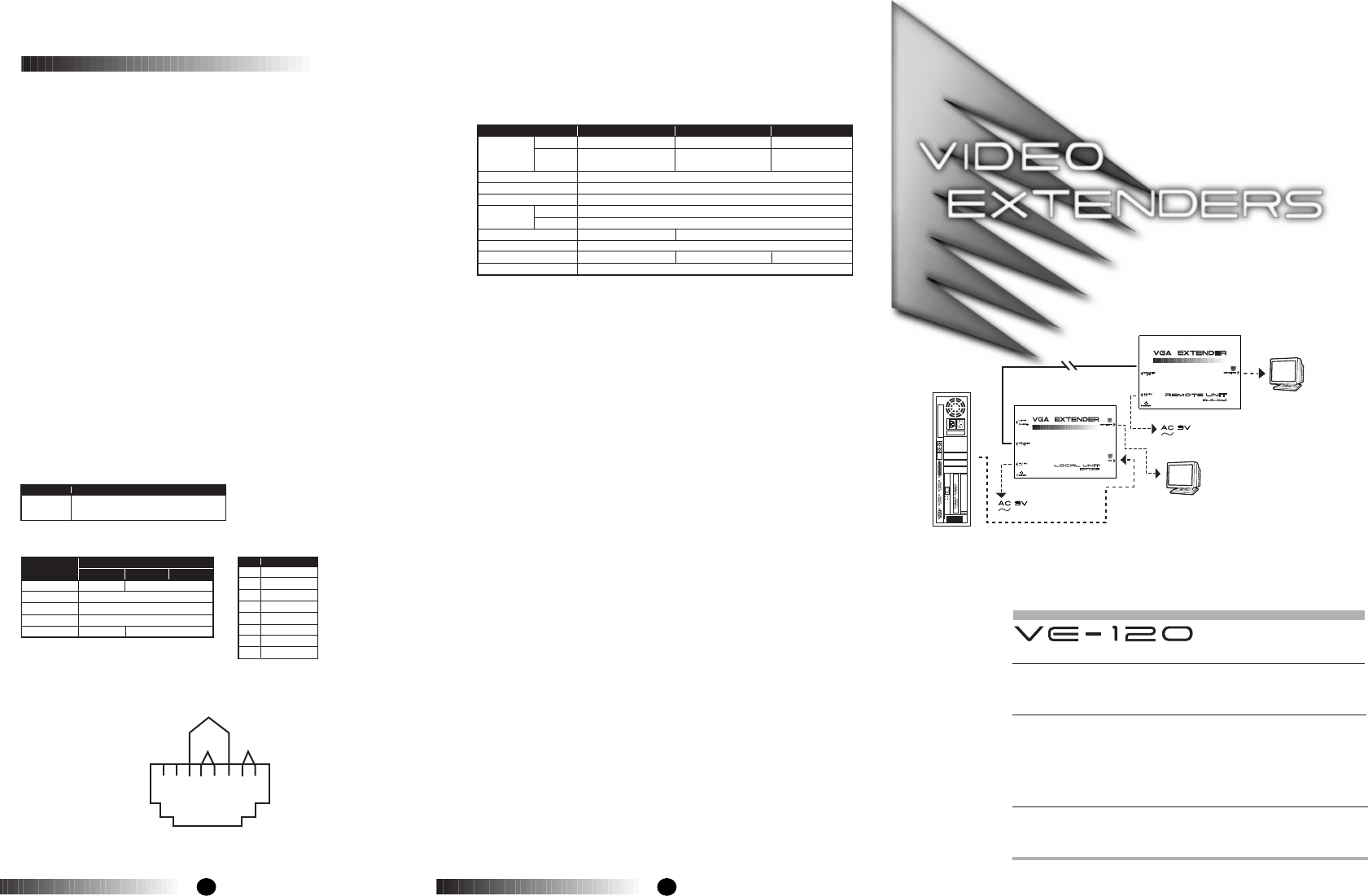
Local Monitor
Remote Monitor
VE-120L
130m
VGA
VE-120R


