


2
3
1
VE-120
VE-120
Overview
The VE-120 Video Extender System allows you to
extend the distance between the computer system
unit and the display monitor by up to 130 meters (430
feet). It accomplishes this by means of a local
transmitting unit (VE-120L), and remote receiving
unit (VE-120R), connected by standard Category 5
twisted pair Ethernet cable.
Note: In order to display the data on more than one
remote monitor, the VE-122 Remote Unit is also
available. While basically similar to the VE-
120R, it incorporates an RJ-45 output jack for
daisy chaining to additional Remote Units.
The VE-120 Video Extender System is ideal for factory
and construction sites, or any installation where the
display needs to reside in a harsh setting, but you
want the system equipment kept in an
environmentally friendly location. The Extender
System is also useful for control and security
purposes, where you can have the system unit in a
secure area at the same time that you put the display
in an area that is convenient for viewing.
Other useful applications for the Video Extender
system include:
•Financial: the remote display of stock market
information
•Education: the remote display of lectures and
lessons to lecture halls and classrooms
•Business: the remote display of addresses to
overflow rooms; video conferencing; and demos
Features
•Uses Category 5 Ethernet Cable: For Economy;
Easy Installation; and Utmost Data Transfer
Reliability
•High Resolution Video - Up To 1600 x 1200@100 m
•Supports VGA, SVGA, and Multisync Monitors
•Long Distance Transmission - Up to 130 m (430')
•Daisy Chainable (VE-122)
System Requirements
•IBM PC/AT, PC Compatible, Notebook, Laptop, or
IBM PS/2 with a VGA output port.
•VGA monitor
•Grounding wire with no potential difference
between the AC sources for the Local and Remote
units.
Warning! Make absolutely sure that a protective
ground wire with no potential difference is
established between the AC sources for
the Local and Remote units. Unequal
grounding potential between the Local
and Remote units will result in damage to
the units and connected devices.
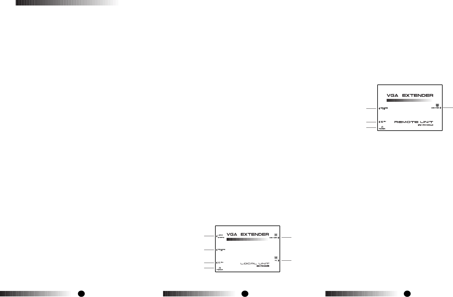
The Local Unit (VE-120L)
1.Range Switch
Slide the switch to the Long position if the Remote
Unit is located a long distance away; slide the
switch to the Short position if the Remote Unit is
located a short distance away.
2.Remote I/O
The Category 5 twisted pair cable that connects to
the Remote Unit plugs into this connector.*
3.AC 9V Power Jack
The power supply cable plugs into this connector.
4.Power LED
Lights to indicate that the unit is receiving power.
5.Monitor
The local monitor's VGA cable plugs into this
connector.
6.PC
The VGA extension cable that connects to the
computer's VGA port plugs into this connector.
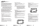
The Remote Unit (VE-120R)
1.Remote I/O
The Category 5 twisted pair cable that connects to
the Local Unit plugs into this connector.*
2.AC 9V Power Jack
The power supply cable plugs into this connector.
3.Power LED
Lights to indicate that the unit is receiving power.
4.Monitor
The remote monitor's VGA cable plugs into this
connector.
Installation
Refer to the diagrams above as you follow the step by
step directions below:
1.Make sure that the computer and monitors you are
using for the installation are all powered Off.
2.Plug the male end of a male to female VGA
extension cable into the computer's video output
port; plug the female end of the cable into the
Local Unit's PC port.
3.Plug the local monitor's VGA cable into the Local
Unit's Monitor port
4.Plug one of the power adapters (supplied with this
package) into an AC source; plug the adapter's
power cable into the Local Unit's AC 9V Power
Jack
5.Plug one end of the Category 5 twisted pair cable
into the Local Unit's Remote I/O port*
1.
4.
2.
3.
1.
2.
3.
5.
6.
4.