


MADE IN THE USA
A PRODUCT OF THE GENFLEX SYSTEM
LINK ELECTRONICS, INC.
ANALOG PULSE GENERATOR
812-OP/K
OUTPUTS
Subcarrier
H Drive
V Drive
For Future Generations
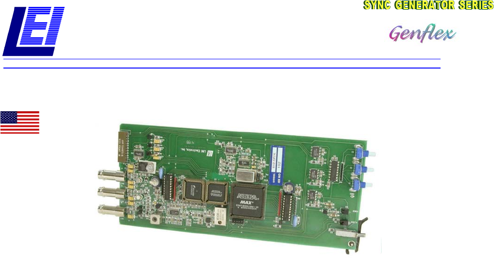
The 812 OP/K is designed to provide H Drive, V
Drive and color subcarrier for system applications
which require 4Vpp drive pulses and 2Vpp
subcarrier. Each of the output pulses is rise-time
controlled to EIA standards and will drive a 75
Ohm load at its specified voltage. The subcarrier
output is filtered for low harmonic distortion and is
driven by a discrete amplifier. The 812 OP/K will
reside in the SPG-812 chassis alongside various
analog and digital modules-up to six modules per
chassis.
When gen-locking to incoming video, the SPG-812
chassis will have either an analog 812 OP/C, gen-
lock to analog black or a 812 OP/D digital genlock
module in slot #2. This module places the timing
pulses down the motherboard buss as reference.
The 812 OP/K pulse generator module then uses
these pulses to lock the PLL on the module and
reset the vertical and horizontal counters within the
complex programmable logic devices. This times
up all counters by an external reference.
When the 812 OP/A analog black burst module,
master timebase, is running in its free-run mode a
front panel control adjusts the frequency of the
Voltage Controlled Crystal Oscillator (VCXO). This
device features a stability of 2.5ppm over the
operating temperature range of 0° to 70° C.
The rear panel view of the SPG-812 is shown on
the back page, showing two 812 OP/H installed in
the cell # 5 and # 6 (as viewed from the rear). An
812 OP/K is installed in cell # 3. Cell #1 is
dedicated for tone, analog and AES. Cell # 2 is
dedicated for gen-lock or the master time base,
812 OP/A, B, C or D. A mixture of analog or digital
in the same frame depends on the specific
module chosen. The rear panel accommodates a
connector for remote control of the test pattern
generator. Two test pattern generators may reside
in the same frame, one local and one remote.
Power supply voltage fault indication is
accomplished by a circuit that monitors all three
supply voltages and turns off the green LED if one
or any is lower then a nominal value.
The PCO-818 automatic pulse change-over modules operate as independent or synchronized operation.
Two PCO-818 change-over chassis may be interlinked to cause all modules to switch should a failure
occur in the master generator.
LINK ELECTRONICS, INC. 2137 Rust Avenue Cape Girardeau, MO 63703-7668
Phone 573 334 4433
FAX 573 334 9255