


Model No.
Quick Installation
Quick Installation
A Division of Cisco Systems, Inc.
®
Model No.
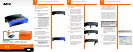
WIRED
BEFVP41 v2
with 4-Port 10/100 Switch
Cable/DSL VPN Router
Package Contents
• Cable/DSL VPN Router
• Setup CD-ROM with User Guide and
Norton Internet Security
• Category 5 Ethernet Network Cable
• Quick Installation
1
Now that you’re familiar with the
Router, follow these instructions for
quick installation.
A
Before you begin, make sure
that all of your hardware is
powered off, including the
Router, PCs, hubs, switches,
and cable or DSL modem.
B
Connect one end of an Ether-
net network cable to one of the
numbered ports on the back of
the Router. Connect the other
end to an Ethernet port on a
network device, e.g., a PC,
print server, hub, or switch.
Repeat this step to connect
more PCs or other network
devices to the Router.
C
Connect your cable or DSL
modem’s Ethernet cable to the
Router’s Internet port.
D
Power on the cable or DSL
modem.
E
Connect the included power
adapter to the Router’s Power
port, and then plug the power
adapter into an electrical out-
let.
The Power LED on the front
panel will light up as soon as
the power adapter is con-
nected properly.
2
Getting to know the Router
In Step 3, you will need the setup
instructions provided by your Inter-
net Service Provider (ISP). If you do
not have this information, then con-
tact your ISP before proceeding.
The instructions from your ISP tell you
how to set up your PC for Internet
access. Because you are now using
the Router to share Internet access
among several computers, you will
use the setup information to config-
ure the Router instead of your PC.
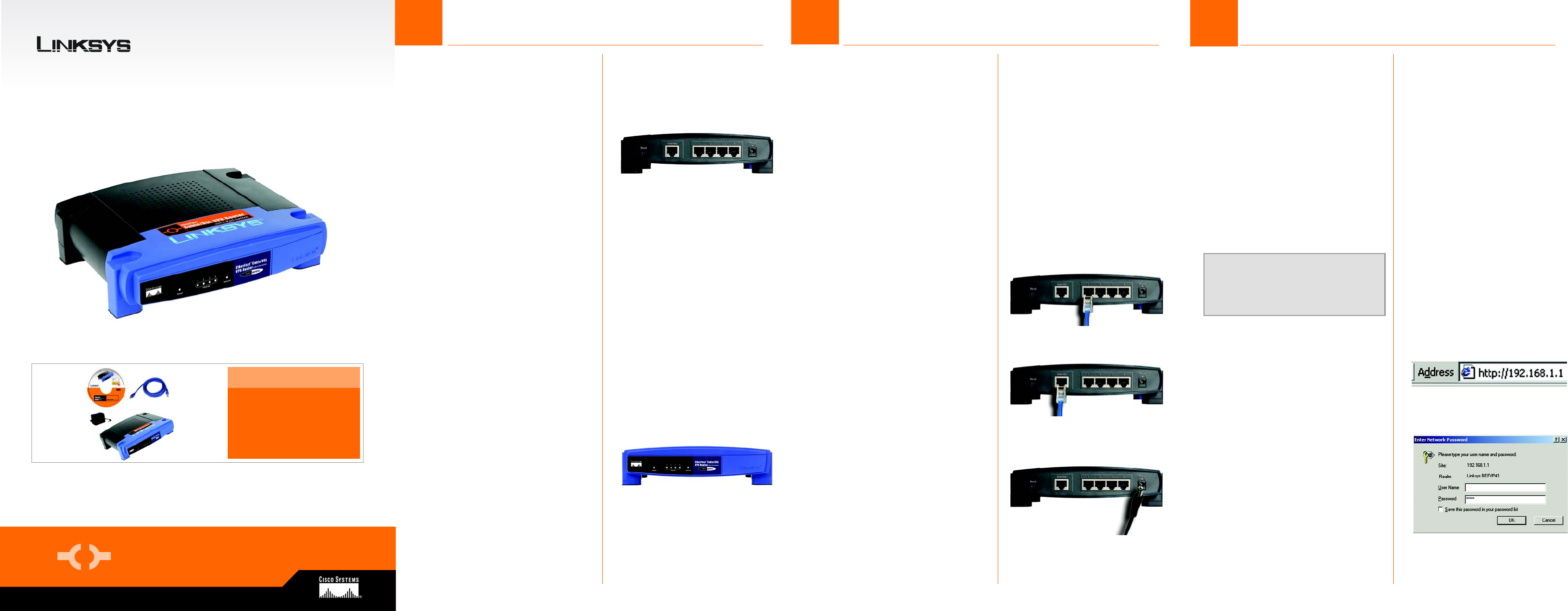
A Open your PC’s web browser.
Enter http://192.168.1.1 (the
Router’s default local IP
address) in the web browser’s
Address field. Then press the
Enter key.
B A screen will appear and ask
you for a User Name and Pass-
word. Leave the User Name
field empty, and enter admin
(the default) in the Password
field. Then click the OK button.
C The Router’s Web-based Utility
will appear with the Basic Setup
screen showing.
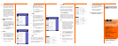
B
Connect the Router
B
A
A
The Back Panel
The Router’s ports and the Reset
button are located on the back
panel of the Router.
Internet
This port connects to your cable or DSL
modem.
1-4
These four ports connect to network
devices, such as PCs, print servers, or
additional switches.
Reset
If the Router is having problems connecting
to the Internet, press the Reset button for
just a second with a paper clip or a pencil
tip, which is similar to rebooting your PC.
If you are experiencing extreme problems
with the Router and have tried all other
troubleshooting measures, press and hold
in the Reset button for 30 seconds. This
will restore the factory defaults and clear
all of the Router’s settings, such as port
forwarding or a new password.
Power
This port is where you will connect the
power adapter.
B The Front Panel
The Router’s LEDs, which inform you
about network activities, are
located on the front panel.
Power
Green. This LED lights up when the Router
is powered on and flashes when the Router
is running a diagnostic test.
Ethernet
Green. This LED shows when the Router is
connected to a device through the
corresponding port (1, 2, 3, or 4) and
flashes when the Router is sending or
receiving data over that port.
Internet
Green. This LED lights up when the Router
is connected to your cable or DSL modem.
EtherFast
®
A
NOTE:: Make sure your PC’s Ethernet
adapter is set to obtain an IP address
automatically. For more information,
refer to Windows Help.
E
C
B
3
Configure the Router