


Powering On the Switch
Plug in the Switch's AC power adapter. Each time your Switch powers up, it
will run a Diagnostic/Self-Test. After the test, the Power LED will light up.
As connections to the Switch’s LEDs are powered on, each port's correspon-
ding Link/Act LED will light up. The remaining LEDs will also light up
according to how your data is being transferred, e.g. full or half duplex,
10mbps or 100mbps.
If the Switch experiences excessive data collisions, verify that your network
cabling is securely crimped and installed properly.
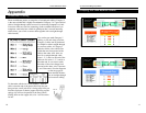
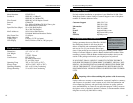
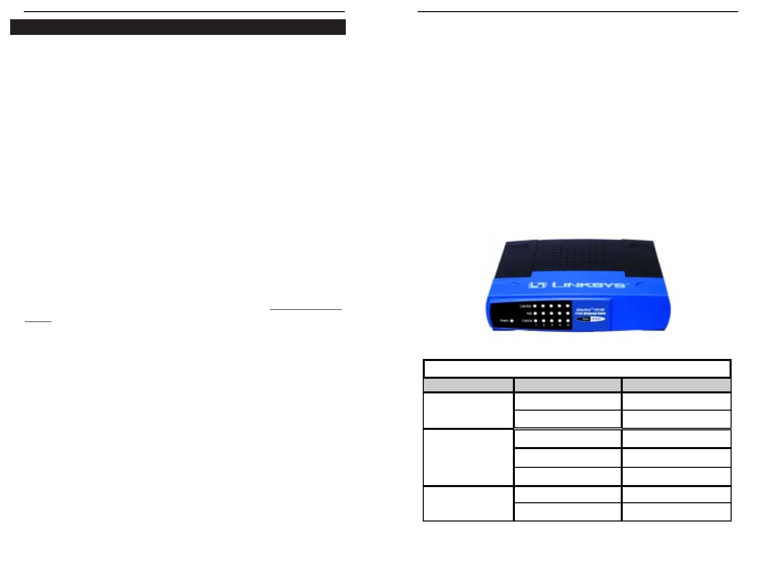
Reading the Front Panel LEDs
The chart below tells you what the front panel LEDs of the 5-Port Switches
mean. Each Switch has a Power LED on the left side to indicate when the
unit is
ON.
Front Panel - EtherFast 10/100 5-Port Workgroup Switch
10/100 5-Port Workgroup Switch
5
Installing Your Switch
Package Contents
Carefully remove your EtherFast 10/100 5-Port Workgroup Switch from its
packaging. Make sure that you have received all of the items listed below. If
any items are missing or damaged, contact your Linksys dealer for replace-
ment part(s).
• EtherFast 10/100 5-Port Workgroup Switch
• AC Power Adapter
• User Guide and Registration Card
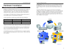
Connecting Computers to Your Switch
Your Switch’s rear panel has five standard RJ-45 ports, plus a shared uplink
port. Each port automatically detects the speed and duplex of the attached
cabling to a network card, switch, hub, etc. The ports operate in either full or
half duplex, which lets you run at speeds of 200mbps, 100mbps, 20mbps or
10mbps.
Each port on your Switch can connect to workstations, file servers, hubs,
repeaters, bridges, routers or other switches. Connections to the switch
require Category 5 UTP network cabling with RJ-45 tips, not to e
xceed 100
meters (328 feet) in length. See page 10 for more details on cabling.
To connect a computer directly to the switch, plug one end of the cable into
the switch, then plug the other end of the cable into the computer's network
adapter.
Uplinking to Other Switches and Hubs
Switches, hubs, and similar network devices are uplinked to your Switch
with straight-through Category 5 cabling. Attach the Category 5 cabling to
the uplink port of the network device that you are uplinking to the Switch,
and plug the other end of the cable into any standard RJ-45 port on your
Switch. Using the uplink port will automatically disable the port directly
next to it, since the uplink port is a shared port.
Instant EtherFast
®
Series
4
LED
LED Status
Network Status
Link/Act
FD/Col
100
On
Flickering
On
Flickering
Off
On
Off
Connection is detected
Data is sending/receiving
Full duplex transfer mode
Port has data collision error
Half duplex transfer mode
100 mbps speed
10 mbps speed
LED Configuration Chart