


15
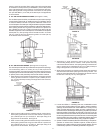
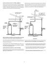
SEDIMENT TRAPS (DRIP LEGS)
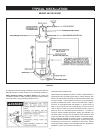
A sediment trap (drip leg) should be installed as close to the inlet of
the water heater as practical at the time of water heater installation.
The sediment trap should be either a tee tting with a capped nipple in
the bottom outlet or other device recognized as an effective sediment
trap. If a tee tting is used, it should be installed in conformance
with one of the methods of installation shown in Figures 11 and 12.
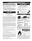
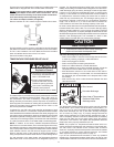
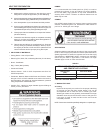
Contaminants in the gas lines may cause improper operation of
the gas control valve that may result in re or explosion. Before
attaching the gas line be sure that all gas pipe is clean on the
inside. To trap any dirt or foreign material in the gas supply line, a
sediment trap (sometimes called a drip leg) must be incorporated
in the piping. The drip leg must be readily accessible. Install in
accordance with the “Gas Piping” section. Refer to the current
edition of the National Fuel Gas Code (ANSI Z223.1/NFPA 54).
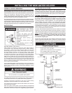
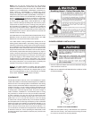
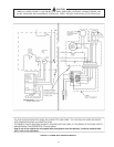
FIGURE 13.
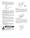
FILLING THE WATER HEATER
Never use this water heater unless it is completely full of water. To
prevent damage to the tank, the tank must be lled with water. Water
must ow from the hot water faucet before turning “ON” gas to the
water heater.
To ll the water heater with water:
1. Close the water heater drain valve by turning the handle to the
right (clockwise). The drain valve is on the lower front of the water
heater.
2. Open the cold water supply valve to the water heater.
NOTE: The cold water supply valve must be left open when
the water heater is in use.
3. To insure complete lling of the tank, allow air to exit by opening the
nearest hot water faucet. Allow water to run until a constant ow is
obtained. This will let air out of the water heater and the piping.
4. Check all water piping and connections for leaks. Repair as
needed.
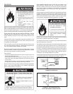
VENTING
VENT PIPE TERMINATION
The rst step is to determine where the vent pipe will terminate, see
Figures 14, 18 and 19. The vent may terminate through the roof as
shown in Figure 19 or through a sidewall as shown in Figure 18.
IMPORTANT
The vent system must terminate so that proper clearances are
maintained as cited in local codes or the current edition of the
National Fuel Gas Code, ANSI Z223.1.
For your convenience instructions on proper installation through a
sidewall are provided in Figure 15 and the numbered points below:
1. The exit terminals of a mechanical vent system should be not less than
7 feet above grade when located adjacent to public walkways.