


NOTES:
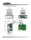
In order for the QDR-TELS to operate properly, the VistaPro 4 and I/O Alarm Board must
already be installed in the PC with particular attention to the items below:
1. The VistaPro 4 main board and I/O board have to be connected each other.(I/O board cable
connector)
2. The power supply port for camera power on the VistaPro main board must be connected to
the PC Power Supply. (Power supply cable)
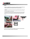
3. The Socket for ‘PC Power On Control’ of the VistaPro I/O Alarm board must be connected to
the Power Pin on the PC main-board (PC Power Pin connection cable -red cable).The other
side of this cable must be connected with the Power Switch connection cable on the front of
PC case.
PC Main-board
PC Main-board
DVR PC Power Pin Cable
DVR PC Power Pin Cable
Power Switch
cable connector
from PC Front case
Power Switch
cable connector
from PC Front case
DVR PC Power Pin
Cable
DVR PC Power Pin
Cable
For further instructions related to the installation of the VistaPro 4 and I/O Alarm Block,
please refer to the VistaPro 4 Installation and User Manual.