


2-2 Installing the LSIU40HVD
Caution: Ground yourself by touching a metal surface before han-
dling boards. Static charges on your body can damage
electronic components. Handle plug-in boards by the edge.
Do not touch board components or gold connector con-
tacts. The use of a static ground strap is recommended.
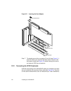
Step 4. Locate the slots for PCI plug-in board installation.
Refer to the user’s manual for your computer to confirm the
location of the PCI slots. The LSIU40HVD requires a PCI slot
which allows bus master operation. See Figure 2.2.
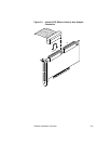
Step 5. Remove the blank panel on the back of the computer aligned
with the PCI slot you intend to use. Save the bracket screw.
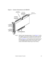
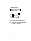
Step 6. Carefully insert the edge connector J1 (see Figure 2.1) of the
host adapter into the PCI slot. Make sure the edge connector
is properly aligned before pressing the board into place. See
the example shown in Figure 2.2.
Note: You may notice that the components on a PCI host adapter
face the opposite way from those on other non-PCI adapter
boards you have in your system. This is correct, and the
board is keyed to go in only one way.
Step 7. The bracket around the connectors J3 and J6 (see Figure 2.1)
should fit where the blank panel was removed. Secure it with
the bracket screw before making the internal and external SCSI
bus connections (see Figure 2.2).
Step 8. If you are connecting any internal SCSI devices, plug a 68-pin
connector on the end of an internal SCSI ribbon cable into
connector J2 or J5 (see Figure 2.1). Make certain to match pin
one on both connectors. Chain the internal devices on this
cable.
Step 9. Connect your computer’s LED cable if desired. This is designed
to drive the front panel LED found on most PC cabinets to
indicate activity on the SCSI bus.
Step 10. Replace the cabinet cover as described in the user’s manual for
your computer.
Step 11. Make all external SCSI bus connections.
Remember: The SCSI bus requires proper termination, and no
duplicate SCSI IDs.