


© LABOR STRAUSS SICHERUNGSANLAGENBAU GMBH • A-1231 WIEN • WIEGELESTRASSE 36 • TEL +43 1 52114-0 • FAX +43 1 52114-27
OFFICE@LST.AT • WWW.LST.AT • ALL RIGHTS RESERVED
LIF128-1_DBL_LST_EN_0915.PDF • PAGE 2
ABuilding Safety. Building Security.
Specifi cations
Current consumption at 24V (without detectors/modules) typ. 25mA
Number of detector zones max. 144
Number of detectors/modules
System Sensor/200 protocol max. 318 elements (159 detectors + 159 modules)
Apollo/Discovery protocol max. 126 elements
Labor Strauss/700 protocol max. 240 elements
Idle loop current typ. 300µA per detector/module
Total loop current max. 500mA (at reduced line resistance)
Idle loop voltage
System Sensor/200 protocol typ. 29V
Apollo/Discovery protocol typ. 26V
Labor Strauss/700 protocol typ. 29V
Loop line resistance max. 50Ω per core
Ambient temperature -5°C to +50°C
Dimensions L × W × H 132 × 74 × 23 (mm)
Weight 80g
Order number 214037
Order name Loop Interface LIF128-1
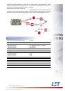
Usually, the loop wiring is realised as ring. Thanks to the
ring-shaped wiring, all elements on the loop keep wor-
king in the event of a single wire breakage. If necessary,
branch lines can also be connected to the ring.
In the event of a short circuit, the functioning of the loop
elements that are cut off from the faulty loop segment
by means of isolators, can be maintained. The control
panel indicates a wire breakage or a short circuit as
loop fault.
Unshielded wires can be used for the fi re detector ca-
bling and, therefore, existing installations can be adop-
ted very easily and existing cabling can be reused.