


PC SPECIFICATION SHEET
101-1773-001 OCTOBER 1999, ISSUE 12
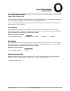
Desktop Platform Backplane Diagram
In the Desktop platform, voice boards are installed starting with the right-hand slot, as viewed from the back of the
PC. On each card, the upper jack is tied to the lowest numbered ports. The example diagram indicates the
connector designations for the DIALOG/4 board. When a single fax board is present, it is installed in the fourth slot
from the right, as viewed from the back of the PC. If two fax boards are present, the first will be in slot three and the
second will be in slot four. Fax ports are marked CH1 (upper) and CH2 (lower) on each board.
The types and number of cards installed will depend on your system configuration. The Network Interface Card
(NIC) is optional.
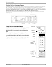
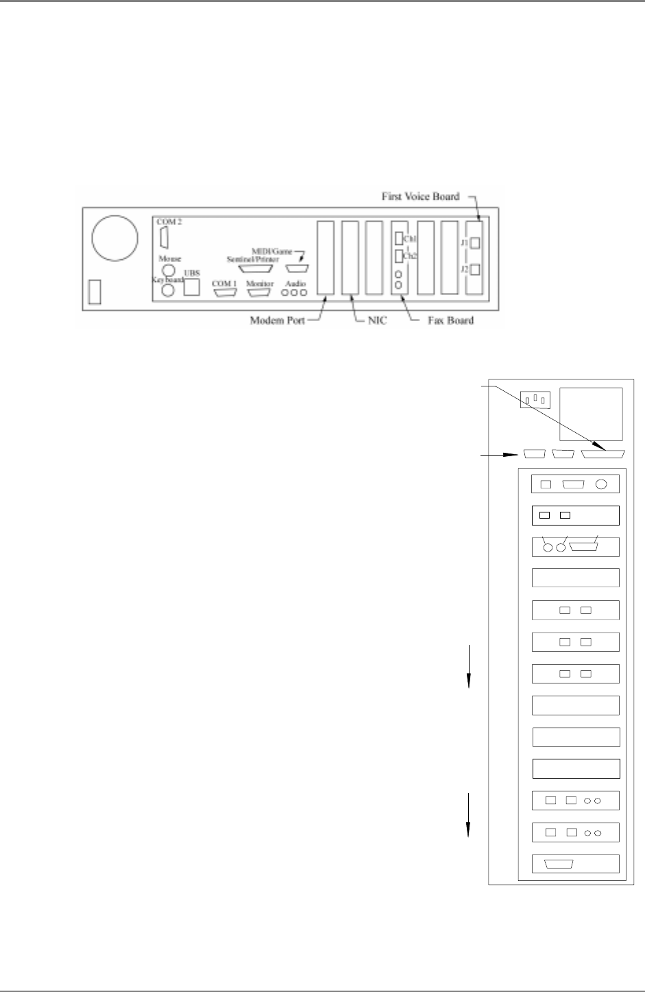
Tower Platform Backplane Diagram
In the Tower platform, voice boards are installed starting with the 5th
slot from the top, as viewed from the back of the PC. On each card,
the left jack is tied to the lowest numbered ports. The example
diagram indicates the connector designations for the DIALOG/4
board.
When a single fax board is present, it is installed in the 12th slot
from the top, as viewed from the back of the PC. If two fax boards
are present, the first will be in slot 12 and the second will be in slot
11. Fax ports are marked CH1 (left) and CH2 (right) on each board.
The types and number of cards installed will depend on your system
configuration. The Network Interface Card (NIC) is optional.
AB
1
13
Serial Board
2
3
4
5
7
8
9
10
11
12
Pwr
J1 J2
6
First Voice Board
Voice Boards
Additional
(when required)
Ch2
Ch1
Fax Board
(1st slot filled)
Fax Board
(2nd slot filled)
(ascending
Fax port #’s)
(ascending
CPU Slot
Modem
Sentinel/Printer
Serial Ports
voice port #’s)
KeyboardMouse Video
(when required)
NIC
(Empty)