


ACM100 User’s Manual
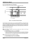
2.4.2.3 Three-Phase (Phase A, B, C) Connection
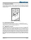
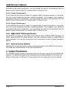
Please refer to Figure 5 for connecting the ACM100 to a three phase system.
Page 8 Revision 1.2
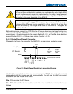
Figure 5 – Three-Phase Connection Diagram
Use the following instructions when you are connecting the ACM100 to a three-phase “Wye”
circuit connected via three hot wires and a single neutral (NOTE: Three-phase delta connected
circuits are not supported by the ACM100). You will need to install three current transformers
and three user-supplied voltage sense cables. The ACM100 comes with a single current
transformer so you will need to purchase two optional current sensors (Part # PCT-1000-101-
03) for monitoring this type of system.
Step 1: De-energize the AC Source.
Step 2: The Current Transformer has black and white wires. Install the first Current
Transformer as follows:
a. Connect the black wire to pin 7 (I
A+
) on the ACM100
b. Connect the white wire to pin 8 (I
A-
) on the ACM100
c. Disconnect the Phase A hot wire from the AC power source and place it through the
hole in the Current Sensor such that the arrow on the Current Sensor points towards
the AC power source. Then, reattach the Phase A hot wire to the AC power source.
Step 3: Install the second Current Transformer as follows:
a. Connect the black wire to pin 9 (I
B+
) on the ACM100
b. Connect the white wire to pin 10 (I
B-
) on the ACM100
Line (Phase A)
Neutral
U.S.
120 Volts
60Hz
+
-
Europe
220 Volts
50Hz
+
-
AC Source
1 2 5436789101112
Fuse
V
A
Line
V
A
Neutral
Current
Transducer
ACM100 Screw Terminals
V
B
Line
V
C
Line
V
B
Neutral
V
C
Neutral
I
A+
I
A-
I
B+
I
B-
I
C+
I
C-
Fuse
Current
Transducer
Fuse
Current
Transducer
Line (Phase B)
Line (Phase C)