


Revision 1.0 Page 5
®®
e. Disconnect the wire from the positive terminal of the battery or other DC source that
is being monitored and place it through the hole in the Current Sensor such that the
arrow on the Current Sensor points towards the battery or DC source. Then,
reattach the wire to the positive terminal of the battery or other DC source.
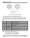
Step 2: The temperature sensor (TR3K) has a gray cable containing red and black wires.
Connect the Temperature Sensor as follows:
a. Connect the red wire to pin 11 (T
A
) on the DCM100
b. Connect the black wire to pin 12 (T
B
) on the DCM100
c. Connect the ring terminal on the Temperature Sensor to the negative terminal of the
battery being monitored
Step 3: The Battery Sense cable (FC01) is a white cable containing one red and one yellow
wire (please note that the same type of cable is used both for the Battery Sense cable and for
the Power cable). Install the Battery Sense cable as follows:
a. Connect the yellow wire from one end of the cable to pin 6 (V
SENS-
) on the DCM100.
b. Connect the yellow wire from the other end of the cable to the negative terminal of
the battery or DC source being monitored (NOTE: this may or may not be the same
as the vessel ground)
c. Connect the red wire from the first end of the cable to pin 5 (V
SENS+
) on the DCM100
d. Connect the red wire from the other end of the cable to the positive terminal of the
battery or DC source being monitored
Step 4: The Power cable (FC01) is a white cable containing one red and one yellow wire.
Install the DCM100 power cable as follows:
a. Connect the yellow wire from one end of the cable to pin 7 (V
PWR-
) on the DCM100.
b. Connect the yellow wire from the other end of the cable to the vessel ground
c. Connect the red wire from the first end of the cable to pin 8 (V
PWR+
) on the DCM100.
d. Connect the red wire from the other end of the cable to a source of 5?-36? VDC
power (NOTE: this wire may nor may not be connected to the same place as the red
wire from the Battery Sense cable).
2.4.3 Checking Connections
Once the NMEA 2000
®
, Current Sensor, Temperature Sensor, Voltage Sense, and DC Power
connections to the DCM100 have been completed, check to see that information is being
properly transmitted by observing an appropriate NMEA 2000
®
display. If you don’t see DC
power data, refer to Section 7, “Troubleshooting”.
2.5 Configuring the DCM100
The DCM100 will transmit data over the NMEA 2000 network as it is shipped from the factory;
however, it does require configuration in almost all cases for proper functioning. There are
several configurable items within the DCM100, including: 1) NMEA 2000
®
DC power instance
selection, 2) Priority Selection, 3) DC Type, 4) Battery Type, 5) Battery Capacity, 6) Nominal
Voltage. 7) Equalization, 8) Temperature Coefficient, 9) Peukert Exponent, 10) Charge
Efficiency Factor, 11) Fully Charged Voltage, 12)Fully Charged Current. 13) Fully Charged
Time. 14) Battery Temperature, 15) Time Remaining Floor, 16) Time Remaining Averaging