


®®
Revision 1.0 Page 5
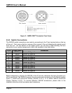
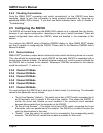
.4.2.1 Switch With End of Line Resistor
M100 to a switch with an end of line resistor.
als
Figure 3 – Switch With End of Line Resistor Connection Diagram
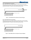
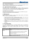
.4.2.2 Switch Without End of Line Resistor
00 to a switch without an end of line resistor.
Figure 4 – Switch Without End of Line Resistor Connection Diagram
2
Please refer to Figure 3 for connecting the SI
This figure shows the connection of the monitored switch to switch channel 1 via the termin
named SW1A and SW1B. Connections to other switch terminals are similar.
8 KΩ end-of-
2
Please refer to Figure 4 for connecting the SIM1
This figure shows the connection of the monitored switch to switch channel 1 via the terminals
named SW1A and SW1B. Connections to other switch terminals are similar.
1 2 5 4 3 6 7 8 9 10 11 12
2B
SIM100 Screw Terminals
SW1A
SW
SW1B
A
4B
SW2A
SW3
SW3B
SW4A
SW
SW5A
SW5B
SW6A
SW6B
Monitored switch
1 2 5 4 3 6 7 8 9 10 11 12
B
SIM100 Scre
SW1A
SW2
w
Terminals
Monitored switch
line resistor
SW1B
SW A
SW3
SW4A
SW4B
SW5A
SW5
SW6A
SW6B
SW2A
3
B
B