


4
Installation and Initial Setup
■
Unpacking
Carefully unpack the V-R1041-IMD-TE4U monitor and verify that the following items are included:
• V-R1041-IMD-TE4U Monitor
• V-PS12-5V-1 Power Supply with 2-Pin Twist Lock Connector
• Operating Instructions
Inspect the unit for any physical damage that may have occurred during shipping. Should there be any damage,
immediately contact Marshall Electronics at (800) 800-6608. If you are not located within the continental United States,
call +1 (310) 333-0606.
■
Installation
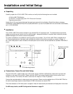
The V-R1041-IMD-TE4U can be mounted in any standard EIA 19” equipment rack. The attached rack ears can be
angled to provide the user control over the viewing angle. Adequate ventilation is required when installed to prevent
possible damage to the monitor’s internal components.
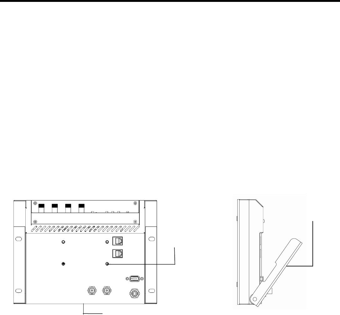
For custom installations, two additional mounting options are provided. The V-R1041-IMD-TE4U is shipped with a
¼”-20 mounting bracket on the bottom side, allowing the monitor to be flexibly mounted to a camera or tripod. A
35 x 75mm hole pattern is also included on the back panel so the monitor can be attached to a standard VESA MIS-C
mount.
■
Connections, Power-On and Initial Setup
Plug the V-PS12-5V-1 power supply into an AC power source (100-240 V @ 50/60 Hz). Attach the 2-pin twist lock
connector to the back of the monitor. Please note that 12VDC can be also supplied directly to the monitor from a
variety of sources. The monitor will draw no more than 2.0 Amps at 12 Volts in operation.
Connect the required cables for video signal input and output. (Power must be applied to the V-R1041-IMD-TE4U for
the active loop-though outputs to be activated.) All BNC connectors are rated at 75Ω.
The screen defaults to ‘ON’ when power is supplied. Video will automatically be detected and displayed on the screen.
For IMD setup details, see IMD Configuration Submenu on page 22.
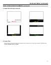
Rack ears on either
side of monitor
VESA MIS
-C
35 x 75mm
hole pattern
¼”-20 Mounting bracket