


21
On-Screen Menu (continued)
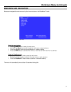
IMD CONFIGURATION SUBMENU (continued)
■
Tally Source
The V-R231-IMD-HDSDI tally (OSD and LED) can be controlled in a variety of different ways. Use the Tally Source
setting to choose how tally is controlled:
Standard
Use the Standard setting to control tally via contact closure on the HD-15 tally interface.
Image Video HW
Use the Image Video HW setting to control Image Video tally states via contact closure on the HD-15 tally
interface. Contact closure of the Red pin corresponds to Image Video Tally 1, and the Green pin maps to Image
Video Tally 2. Contact closure (ground) corresponds to a LOW state, and open circuit corresponds to a HIGH
state. This mode requires the IMD Tally Mode parameter to be set. Consult Image Video documentation for
further information.
Image Video 422
Use the Image Video 422 setting to control Image Video tally states via the Image Video serial protocol. LED and
OSD tally will be disabled in this mode, as Image Video tally states are manifested in the text color and other
parameters. This mode requires the IMD Tally Mode parameter to be set. Consult Image Video documentation for
further information.
Standard + IV422
Use the Image Video 422 setting to control Image Video tally states via the Image Video serial protocol, while
controlling LED and OSD tally using contact closure on the HD-15 tally interface. This mode requires the IMD
Tally Mode parameter to be set. Consult Image Video documentation for further information.
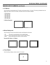
TSL/Marshall 422
Use the TSL/Marshall 422 setting to control OSD and LED tally via the TSL or Marshall serial protocols.
■
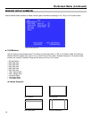
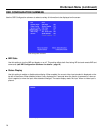
IMD Tally Mode
Use this setting when using Image Video tally control. Choose one of the following settings, in conjunction with the
Image Video controlling device. T1, T2, T1T2, T2T1, T1-, T2-, T1T2-, T2T1-. Consult Image Video documentation for
further information.
SERVICE SUBMENU
■
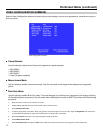
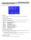
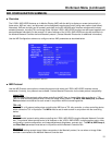
Overview
The Service submenu displays the status of the serial interface, for troubleshooting or debugging purposes only.
Contact Marshall Electronics for further information. The following information is displayed:
• Serial Characters Rx: Total number of characters received by the UART
Tx: Total number of characters transmitted by the UART
• Serial Errors P: Number of parity errors
F: Number of framing errors
O: Number of FIFO overrun errors
• Packets Rec: Number of packets received
Exe: Packets Executed
• Packet Errors CRC: Number of packets that failed CRC check
Err: Number of other packet errors
• Last Command R: Last command received
E: Last command executed
• Software State State: 000:000 1010111 (correct value)