


3
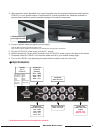
3. After inspection, attach adjustable rear support brackets using the supplied thumbscrews and install the
V-RD151-4 in your desired location of a standard EIA 19-inch equipment rack. Adequate ventilation is
required when installed to prevent possible damage to the internal components.
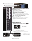
S-Video IN
4 Pin Din
(Female)
Pin1 - GND
Pin2 - GND
Pin3 – Y in
Pin4 – C in
VGA IN
HD-15
(FEMALE)
Pin1-Red IN
Pin2-Grn IN
Pin3-Blu IN
Pin4-
Pin5-
Pin6-Gnd
Pin7-Gnd
Pin8-Gnd
Pin 9-
Pin10-
Pin11-
Pin12-
Pin13-
Pin14-HSync
Pin15-VSync
Composite
Video IN 1 to 4
Attached bracketThumbscrews and
rear support bracket
Input Connectors
6
Active Composite
Video out 1 to 4
12 VDC from
V-PS12-5V1 power
supply
Left Pin - Pos
Right Pin- Neg
S-Video OUT
4 Pin Din (Female)
Pin1 - GND
Pin2 - GND
Pin3 – Y in
Pin4 – C in
* All Outputs Require Power to be applied for activation
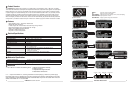
4. Connect required cables for signal input and output.
5. Plug the V-PS12-5V1 power supply into the A.C. source.
6. Attach the twist lock Conxal power connection from V-PS12-5V1 power supply to the back of the drawer.
7. Completely Slide the V-RD151-4 out from the drawer and tilt to your desired viewing angle.
8. Turn on the V-RD151-4 by depressing the power switch located on the front of the unit.
Note: All BNC connectors should be rated for 75Ω.
Note: Power must be applied to the V-RD151-4 to activate loop through video connections
Marshall Electronics