9
106813
OWNER’S MANUAL
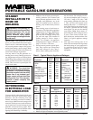
Ampere AWG for Length of
Load Cord in Feet
50' 100' 150'
2181818
3181818
4161616
5161616
6161614
8161412
10 16 14 12
12 14 14 12
14 14 12 10
16 12 12 10
20 10 10 8
FUE
L
F
F
F
U
E
L
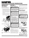
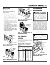
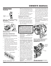
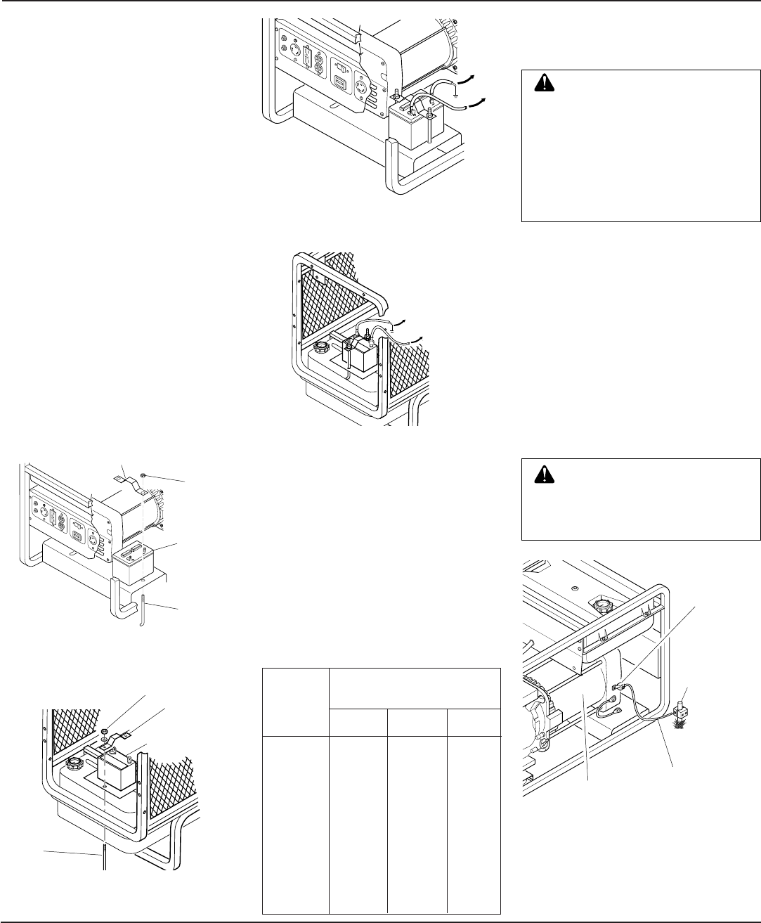
Figure 12 - Battery Hold-Down System
(Model MGH6500IE Shown)
TO STARTER
SOLENOID
TO ENGINE
BLOCK
120
O
NL
Y
120
240V
E
N
M
0
00
0
00
0
5
H
O
U
RS
1/
10
F
UL
L
P
O
W
E
R
Figure 14 - Connecting Positive and
Negative Cables to Battery
(Model MGH6500IE Shown)
BATTERY
Continued
Figure 13 - Battery Hold-Down System
(Model MGH10000A Shown)
Battery
Mounting
Bracket
F
F
U
E
L
Figure 15 - Connecting Positive and
Negative Cables to Battery
(Model MGH10000A Shown)
TO STARTER
SOLENOID
MOUNTING BATTERY TO
GENERATOR
1. Secure battery to generator by battery
hold-down system. This system con-
sists of the battery mounting bracket,
hook bolts, and nut (see Figure 12).
Note:
Model MGH10000A battery is
located on opposite side as shown (see
Figure 13).
2. Locate the red, positive (+) battery
cable from starter solenoid. Connect it
to the positive (+) battery terminal (see
Figures 14 and 15).
3. Locate the black, negative (–) battery
cable attached to engine block. Connect
it to the negative (–) battery terminal
(see Figures 14 and 15).
4. Check battery before starting engine.
Make sure fluid levels are full. Make
sure battery is charged.
See engine owner’s manual for more
information.
Battery
Hook
Bolt
Nut
GENERATOR
GROUNDING
Ground Lug
Ground Wire
Alternator
Copper or
Brass
Grounding
Point
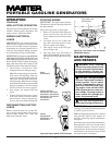
Figure 16 - Grounding Generator
(Model MGH4000C Shown)
EXTENSION
CORDS
Only use grounded extension cords. Be sure
to use extension cord with proper wire gauge
size. See chart below.
Recommended Minimum Wire
Gauges (AWG) for Extension
Cords
1
2
0
O
N
L
Y
1
2
0
2
4
0
V
E
N
M
0
0
0
0
0
0
0
5
H
O
U
R
S
1
/
1
0
F
U
L
L
P
O
W
E
R
Battery Mounting Bracket
Battery
Hook Bolt
Nut
TO ENGINE
BLOCK
WARNING: For a grounding
point, do not use metal pipe be-
ing used to carry combustible
materials or gases.
Grounding generator helps prevent electric
shock from a ground fault condition. Locate
ground lug on end of generator housing (see
Figure 16). Attach a #10 stranded-copper
ground wire to ground lug. Drive grounding
point into ground. Grounding point can be a
stake, grounding rod, or pipe. Grounding
point should be copper or brass. Attach
ground wire to grounding point. You must
supply the ground wire and grounding point.
These do not come with generator. Follow
the National Electrical Code and all state
and local codes. Consult your power com-
pany or a licensed electrician.
WARNING: You must prop-
erly earth-ground generator be-
fore starting. This will help guard
against deadly electric shock.
Only use grounded plugs with
generator. Only use grounded ex-
tension cords. Only use three-
wire or double-insulated power
tools.


