


USBTO232
2 _______________________________________________________________________________________
Quick Start
The following instructions are for installing USB drivers
and the EV kit software. Once the USB drivers and EV
kit software have been installed, refer to the
Quick Start
section of the appropriate EV kit data sheet for EV kit-
specific instructions.
Recommended Equipment
• USBTO232 board (USB cable included)
• Maxim EV kit (or EV system) with a COM port PC
connection
• Corresponding EV kit data sheet
• User-supplied PC with a USB port
Note: In the following sections, software-related items
are identified by bolding. Text in bold refers to items
directly from the EV kit software. Text in bold
and
underlined refers to items from the Windows
98SE/2000/XP operating system.
Procedure
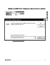
1) Visit the Maxim website (www.maxim-ic.com/evkit-
software) to download the latest version of the EV
kit software that supports USB. Save the EV kit soft-
ware to a temporary folder and uncompress the file,
if it is a .zip file.
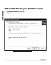
2) Install the EV kit software on your computer by run-
ning the INSTALL.EXE program inside the tempo-
rary folder. The program files are copied to
C:\Program Files\MAXxxxxx and icons are creat-
ed in the Windows Start | Programs
menu.
3) Uncompress the USB driver file copied into
C:\Program Files\MAXxxxxx after the software is
installed. If you are using Windows 98SE, uncom-
press the USB_Driver_98_ME_V1.09.zip file. If you
are using Windows 2000/XP, uncompress the
USB_Driver_XP_2K_V2.00.zip file. Uncompress
the contents of the .zip file into C:\Program
Files\MAXxxxxx.
4) Verify that the following USBTO232 jumpers are in
the default positions:
JU1: (1-2)
JU2: (2-3)
JU3: (2-3)
5) Connect the included USB cable from the PC’s USB
port (Type A) to the Type B USB connector on the
USBTO232 board.
6) Verify that the red VCC power LED (D1) lights up.
Also verify that the green VCCIO power LED (D2)
lights up.
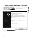
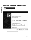
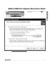
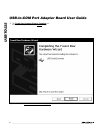
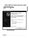
7) Go to the appropriate USB
Driver Installation
sec-
tion in this data sheet for the version of Windows
you are using and return to step 8 when finished.
For example, if you are using Windows XP, go to
the
Windows XP USB Driver Installation
section.
Windows XP: Page 3
Windows 2000: Page 11
Windows 98SE: Page 25
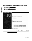
8) Connect the USBTO232 board to the EV kit (or EV
system) by connecting the male DB9 connector on
the USBTO232 board to the female DB9 connector
on the EV kit.
9) Refer to the
Quick Start
section of the appropriate EV
kit data sheet for further EV kit-specific instructions.
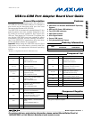
Detailed Description of Hardware
The USBTO232 is an adapter board that converts a
PC’s USB port into a standard COM port. The
USBTO232 board has three configurable jumpers: JU1,
JU2, and JU3. Jumper JU1 is the I/O supply selection
(see Table 1), jumper JU2 is the USB power-supply
indicator (see Table 2), and jumper JU3 is the 3.3V
power-supply indicator (see Table 3).
Table 1. I/O Supply Selection (VCCIO)
*
Default position.
Table 2. USB Power-Supply Indicator
(VCC–D1)
*
Default position.
Table 3. 3.3V Power-Supply Indicator
(VCC30–D2)
*
Default position.
JUMPER SHUNT POSITION DESCRIPTION
1-2* VCCIO = VCC = 5V
JU1
2-3 VCCIO = VCC30 = 3.3V
JUMPER SHUNT POSITION DESCRIPTION
1-2
General-purpose LED
connected to CBUS0
JU2
2-3*
Indicates USB power present
when red LED (D1) is lit
JUMPER SHUNT POSITION DESCRIPTION
1-2
General-purpose LED
connected to CBUS1
JU3
2-3*
Indicates regulated 3.3V
power present when green
LED (D2) is lit
USB-to-COM Port Adapter Board User Guide