


4
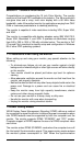
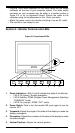
• Plug the 15-pin male connector on the video cable into the output
connector on the rear of your computer system. The video output
connector on your computer may be either in a location similar to
Figure 2-2
or on an expansion board. Secure the cable to the
computer using the thumbscrews on the 15-pin connector.
• Attach the power cord to the monitor and plug it into an AC outlet.
• The monitor is now ready for use.
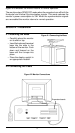
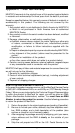
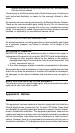
Section 3 - Monitor Controls and LEDs
1. Power Indicators: LEDs A and B indicate the state of the Monitor.
• LED A On (green) Normal operations.
• LED A flashing DPMS (Display Power Management Signaling)
“STAND-BY” mode.
• LED B On (orange) DPMS “OFF” mode.
2. Power Switch: Push to turn the monitor ON, push again to turn the
monitor OFF.
3. Trapezoid: Adjusts the angle of the sides of the display to make the
display rectangular.
4. Pincushion: Adjusts the curvature of the sides of the display to make
the sides straight.
5. Vertical-Position: Adjusts the vertical position
A
B
1
2
34 567 1098
Figure 3-1 Controls and LEDs