


INSTALLATION
4 – 18
6
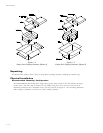
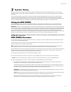
Attaching System Cables
The computer system the Maxtor hard drive is being installed in will have its own cable placement and connection methods. This means that the location of
the IDE interface connectors on the mother board and/or interface card and the orientation of pin one is determined by the manufacturer. Also, older systems
and interface cards may have only a single IDE interface connection – limiting the system to two IDE devices. Refer to the system or interface card user’s
manual for cable connection and orientation instructions.
Attach the 40-pin IDE interface cable from the Maxtor hard drive to the IDE connector on the mother board or IDE interface card. Insure that the red edge of
the ribbon cable is oriented to pin 1 on the interface.
5
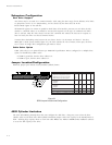
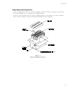
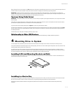
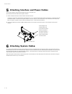
Attaching Interface and Power Cables
In order for the computer to recognize that the Maxtor hard drive is in the system, the
power cable and IDE interface cable must be properly connected.
1 Attach an available IDE interface connector to J1 on the Maxtor hard drive.
The striped or colored edge of the IDE interface cable indicates pin 1. Pin 1 on the IDE interface cable connector must match pin 1 on the Maxtor hard drive
IDE interface connector – closest to the drive power connector. It must also match pin 1 on the IDE connector on the mother board or IDE interface card.
Refer to the system or interface card user’s manual for identification of pin 1 on their IDE interface connector.
2 Connect an available power connector to J2 on the Maxtor hard drive. This connector is keyed and will only fit in one orientation. Do not force the
connector.
After attaching the IDE
interface cable and the
power cable to the Maxtor
hard drive, verify that all
other cables connected to
other devices, the mother
board or interface card(s)
are correctly seated.
Striped/colored edge is pin