


PC-CARD-DAS16/12AO User's Guide Specifications
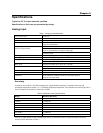
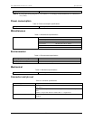
Digital input/output
Table 9. DIO specifications
Digital type FPGA
Number of I/O 4
Configuration One port, programmable
4 input / 4 output
Input low voltage 0.8 V max
Input high voltage 2.0 V min
Output low voltage (IOL = 4 mA) 0.32 V max
Output high voltage (IOH = -4 mA) 3.86 V min
Absolute maximum input voltage -0.5 V , +5.5 V
Power-up / reset state Input mode (high impedance)
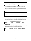
Interrupt
Table 10. Interrupt specifications
Interrupts Programmable: Levels 2 – 15
Interrupt enable Programmable. Default = disabled.
External (External Interrupt)
A/D End-of-channel-scan
A/D FIFO-not-empty
A/D FIFO-half-full
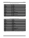
Interrupt sources
A/D Pacer
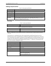
Counter
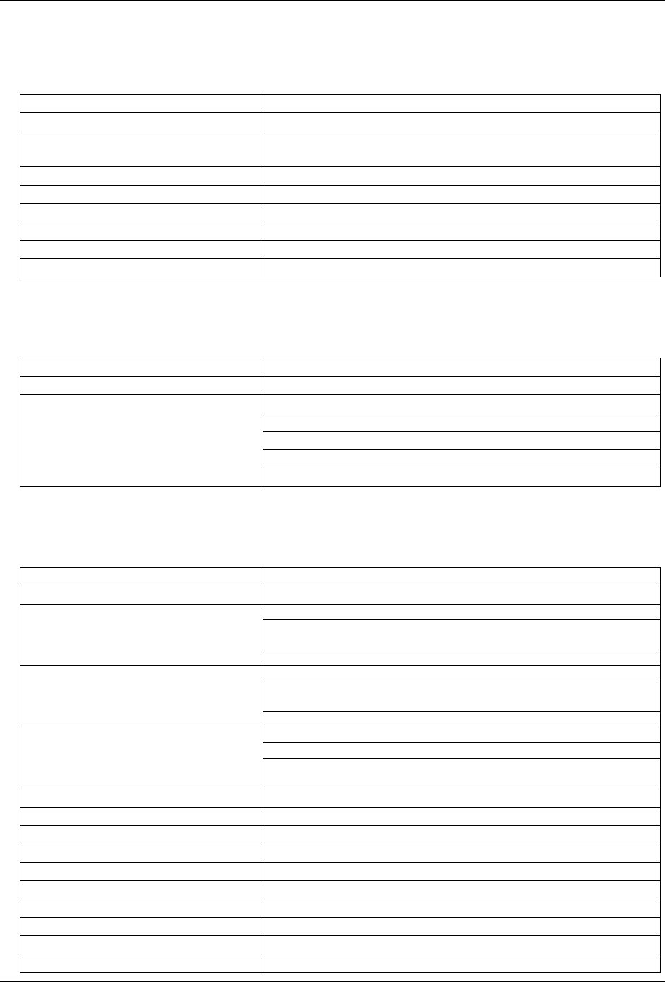
Table 11. Counter specifications
Counter type 82C54
Configuration 3 down counters, 16 bits each
Source: Programmable external (Ctr 1 Clk) or 100kHz internal source
Gate: Available at connector (Ctr 1 Gate), pulled to logic high via 10K
resistor. See Note 2.
Counter 1 - User counter
Output: Available at connector (Ctr 1 Out)
Source: Programmable, 1MHz or 10 MHz internal source
Gate: Available at connector (A/D Pacer Gate), pulled to logic high
via 10K resistor.
Counter 2 - ADC Pacer Lower Divider
Output: Chained to Counter 3 Clock
Source: Counter 2 Output
Gate: Internal
Counter 3 - ADC Pacer Upper Divider
Output: Programmable as ADC Pacer clock. Available at user connector
(ADC Pacer out)
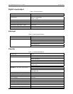
Clock input frequency 10 MHz max
High pulse width (clock input) 30 ns min
Low pulse width (clock input) 50 ns min
Gate width high 50 ns min
Gate width low 50 ns min
Input low voltage 0.8 V max
Input high voltage 2.0 V min
Output low voltage 0.4 V max
Output high voltage 3.0 V min
Crystal oscillator frequency 10 MHz
23