


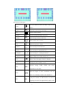
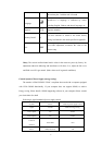
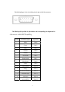

The following figure is the view looking into the pin end of video connector
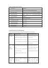
The following table provides the pin numbers and corresponding pin assignments for
video connector with the DDC2B capability::
Number RGB Mode Signal Signal Pin
1 RED Pin# 1
2 Green Pin# 2
3 Blue Pin# 3
4 Ground Pin# 4
5 Ground Pin# 5
6 Red Ground Pin# 6
7 Green Ground Pin# 7
8 Blue Ground Pin# 8
9 Empty Pin# 9
10 Sync Ground Pin# 10
11 Empty Pin# 11
12 Bi-Directional Data(SDA) Pin# 12
13 Horizontal Sync Pin# 13
14 Vertical Sync Pin# 14
15 Data Clock(SCL). Pin# 15
9