


700 Elmont Rd, Elmont, NY 11003, Tel: 516-285-1000; Fax: 516-285-6300
www.Meridian-tech.com
Page 6 3/07 Rev 1.2
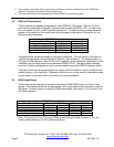
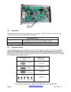
3.5 Connectors
The tables below identify the various connectors on the modules. The DVI-I connector is mounted to the
module’s front panel on both the transmitter and receiver.
Connectors
Video Standard DVI-I female (with RGBHV analog inputs/outputs)
DVI-I to RGBHV (HD-15 female) molded adapter (dongle)
RGB adjustment 4-pin USB (type B)
Optical Multimode - ST
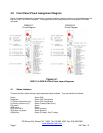
3.6 Conversion Cables
There are several types of DVI connectors that are mounted on standard computers and monitors. Meridian
offers standard adapter cables (6 ft length) to properly interface these various connectors to our RGB-T/R
modules. The table below identifies the type of connectors and the corresponding Meridian adapter cable that
should be used. The connector on the opposite end of the cable is the standard DVI-I connector that interfaces
to the RGB transmitter/receiver modules.
HD15(M)
DVI-I
Connector
DVI-D
Connector
Computer/Input/Output
Device
Adapter Cable
Part Number
Red Grn Blu H-Syn V-Syn
C-HD15-6
C-DVI-I-6
C-DVI-D-6
C-BNC-6
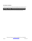
BNC Connectors
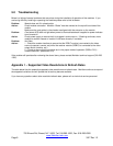
Switch #1
Switch #2