


12 User Guide
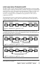
Link Loss Return (LLR)
The fiber ports on the “twister” have been designed with Link Loss Return function-
ality for troubleshooting remote connections. When LLR is enabled
*
, the port’s
transmitter (TX) shuts down if its receiver (RX) fails to detect a valid receive link.
LLR should only be enabled on one end of a cable and is typically enabled on either
the unmanaged or remote device. LLR works in conjunction with LLCF and CLCF.
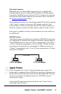
The diagram below shows a typical network configuration with good link status
using two “twister” units for remote connectivity. Note that LLR and LLCF are
enabled as indicated in the diagram.
*Units are shipped with LLR disabled (OFF). On the copper-to-fiber boards, LLR is always enabled on the copper port and
cannot be disabled.
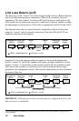
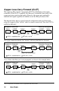
Example: If one of the optical conductors breaks (as shown in the diagram box
below), “twister” B, with LLR2 enabled, will return a no-link condition to its link
partner, “twister” A. On the fiber-to-fiber models with LLCF also enabled on both
units, the no-link condition is carried forward to the switch/hub where a trap is
generated to the management station. The network administrator can then determine
the source of the loss.
Management
Station
Remote
Station
Switch/Hub
w/SNMP
Switch/Hub
w/SNMP
“twister”
A
“twister”
B
Link Loss Returned
Link Loss Carried Forward
Link Loss Carried Forward
LED lit = established link LED unlit = no link
Broken
Conductor
LLCF is ON
LLR2 is ON
LLR1 is OFF
LLCF is ON
LLR2 is ON
LLR1 is OFF
Port 2
Port 1
Management
Station
Remote
Station
Switch/Hub
w/SNMP
Switch/Hub
w/SNMP
“twister”
A
“twister”
B
Remote
Cable
LED lit = established link LED unlit = no link
LLCF is ON
LLR2 is ON
LLR1 is OFF
LLCF is ON
LLR2 is ON
LLR1 is OFF
Port 2 Port 1
Port 2 Port 1
IMPORTANT: LLR must not be active on both ends of a configuration. If it is, the
link can never be established.