


10 Installation Guide
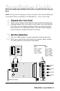
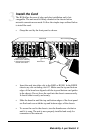
Connect to the Network
To connect the R104 to the network, insert the twisted-pair cables into
the appropriate connectors. Be sure the card is secured to the chassis by
tightening the thumbscrew before making network connections.
The R104 provides four shielded RJ-45 connectors that support a
maximum segment length of 100 meters. Use Category 3, 4 or 5 cables
for 10Mbps segments; use only Category 5 or 5E cables for 100Mbps
segments.
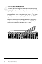
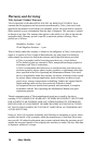
Insert your connectors as shown below. Once power is applied to the
card, correct connectivity can be verified via the link (LK) LED, if an
active device is connected to the remote end of the cable.
RX
LK
TX
FX
M
M
II
x
PWR
100 FD
RX
LK
T
X
TX
10/100
AT
LK
2
PWR
AT
LK
1
LK
10/100 BASE
RX
LK
TX
FX
M
M
II
x
PWR
100 FD
RX
LK
T
X
TX
10/100
RX
LK
TX
BWDM
II
x
PWR
100FD
RX
LK
T
X
TX
10/100
II
x
PWR
100 FD
RX
RX
LK
LK
T
X
M
M
FL
TX
TX
10/100
II
x
II
x
PWR
100 FD
100 FD
RX
RX
LK
LK
T
X
T
X
TX
TX
10/100
RX
LK
TX
FX
M
M
II
x
PWR
100 FD
RX
LK
T
X
TX
10/100
RX
LK
TX
FX
M
M
II
x
PWR
100 FD
RX
LK
T
X
TX
10/100
MM
RX
LK
TX
II
x
100
FD
RX
LK
T
X
TX
10/100
MGT-10
LK
AT
C
O
N
S
O
L
E
1
PWR
A
B
R
ER
FX
PWR
RX
RX
LK
LK
M
M
FL
TX
TX
10/100
M
M
RX
RX
LK
LK
TX
TX
10/100
SM
II
x
T
X
100 FD
FD
RX
LK
TX
FX
M
M
II
x
PWR
100 FD
RX
LK
T
X
TX
10/100
RX
LK
TX
FX
M
M
II
x
PWR
100 FD
RX
LK
T
X
TX
10/100
RX
LK
TX
SM
II
x
100
FD
RX
LK
T
X
TX
10/100
RX
LK
TX
FX
M
M
II
x
PWR
100 FD
RX
LK
T
X
TX
10/100
RX
LK
TX
FX
M
M
II
x
PWR
100 FD
RX
LK
T
X
TX
10/100
4
3
AT
LK
LK
AT
2
4