


Radiance SONET Single Interface Line Cards 5
Installation Guide
Follow the simple steps outlined in this section to install and start using
your Radiance SONET single interface line card.
NOTE: Electrostatic discharge precautions should be taken when handling any
line card. Proper grounding is recommended (i.e., wear a wrist strap).
Unpack the Line Card
Your order has been provided with the safest possible packaging, but
shipping damage does occasionally occur. Inspect your line card
carefully. If you discover any shipping damage, notify your carrier and
follow their instructions for damage and claims. Save the original
shipping carton in case return or storage of the unit is necessary.
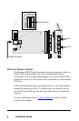
Set the DIP Switches*
A set of six DIP switches is located on the back of the line card. (See
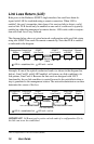
illustration.) Two of these switches are used to enable/disable Link
Loss Return (LLR) and are clearly marked LLR1 and LLR2 on the
printed circuit board.
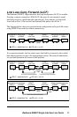
The remaining switches, including the one labeled LLCF, are nonfunc-
tional. Pushing these switches up and down has no effect. Link Loss
Carry Forward (LLCF) is a feature that is always enabled.
When setting DIP switches, the UP position is when the lever of the
DIP switch is pushed away from the circuit board. The DOWN position
is when the lever is pushed toward the circuit board.
The default switch settings are LLR1 disabled (DOWN) and LLR2
disabled (DOWN).
*DIP switches also can be controlled by console commands or with Metrobility’s NetBeacon or WebBeacon management
software. Refer to the
Command Line Interface Reference Guide
,
NetBeacon Element Management Software Installation & User’s
Guide
or
WebBeacon Management Software Installation & User’s Guide
for software management information.
1
2