32
1 10
APPENDIX C
Scanner Pinout Connections
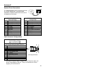
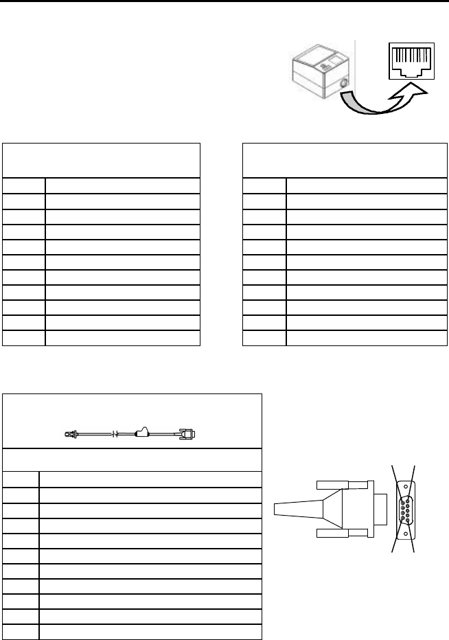
The IS6520/MS6520 scanner interfaces terminate
to a 10-pin modular jack. The serial # label
indicates the interface enabled when the scanner
is shipped from the factory.
IS6520-47 / MS6520-47
Keyboard Wedge
IS6520-41 / MS6520-41
RS-232/LTPN
Pin Function Pin Function
1 Ground 1 Ground
2 RS-232 Transmit Output 2 RS-232 Transmit Output
3 RS-232 Receive Input 3 RS-232 Receive Input
4 PC Data 4 RTS Output
5 PC Clock 5 CTS Input
6 KB Clock 6 DTR Input/LTPN Source
7 PC +5V 7 Reserved
8 KB Data 8 LTPN Data
9 +5VDC 9 +5VDC
10 Shield Ground 10 Shield Ground
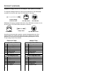
Cable Connector Configurations
“Standard” PowerLink cable
(MLPN 53000 or 54000)
9-pin D-type female connector to the PC
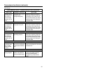
Pin Function
1 Shield Ground
2 RS-232 Transmit Output
3 RS-232 Receive Input
4 DTR Input
5 Power/Signal Ground
6 Light Pen Data
7 CTS Input
8 RTS Output
9 +5VDC*
* If a PowerLink power supply is plugged into the PowerLink cable, +5V
will NOT be available on this pin. This pin is used when the host is
supplying +5V to the scanner.
9-Pin D-Type Connector
6 1
9 5


