


50
SCANNER AND CABLE TERMINATIONS
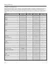
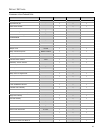
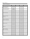
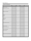
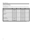
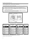
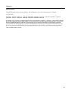
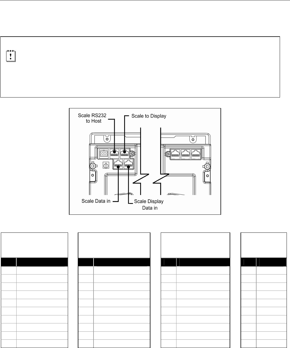
SCALE READY MS2421 MODELS – ADDITIONAL PINOUT CONNECTIONS
There are four additional 10-pin modular jacks located on the bottom of the of the MS2421 scanner models that may be used
for an integrated scale application and the use of a remote display.
Please keep in mind that every application is unique. The use of these connections depends on the
specifications of the scale’s manufacturer. The following pinouts are for reference only. If the scanner has
been integrated with a scale, refer to the Scale Addendum for detailed instructions on the appropriate cable
connections, communication specifications and calibration procedures required by the scale manufacturer and
local Weights and Measures authorities.
When connecting any combination of scale/external scale display to the M2421 do not exceed the
following current restrictions: 12V @ 0.7A max. / 5V @ 0.2A max.
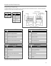
Figure 38. Scale Ready Connector Layout
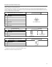
Scale Display Data In Scale
Data to Display from the Load
Cell Interface
Scale Data In
RS232 from the Load Cell
Interface
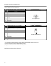
Scale RS232 to Host
Scale Data, Dual Cable
Applications
Scale to
Display
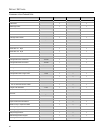
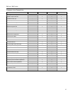
Pin
Function
**
Pin
Function
**
Pin
Function
**
Pin
Function
**
1 SIG1 1 12V 1 Ground 1 SIG1
2 SIG2 2 Ground 2 Scale RS232 TX Out 2 SIG2
3 SIG3 3 5V 3 Scale RS232 RX In 3 SIG3
4 SIG4 4 Ground 4 Scale RS232 RTS Out 4 SIG4
5 SIG5 5 RS232 TX In 5 Scale RS232 CTS In 5 SIG5
6 SIG6 6 RS232 RX Out 6
No Connect
6 SIG6
7 SIG7
††
7 RS232 CTS In 7
No Connect
7 SIG7
††
8 SIG8
††
8 RS232 RTS Out 8
No Connect
8 SIG8
††
9 SIG9
††
9 Scale Status, TTL 9
No Connect
9 SIG9
††
10 SIG10
††
10 Scale Zero, TTL 10 Shield 10 SIG10
††
** All signals are referenced from the MS2421/MS2422 scanner.
††
The use of these pins depends upon the specifications of the scale’s manufacturer.
Specifications are subject to change without notice.