


36
Appendix C
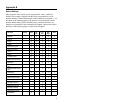
Pin Assignments
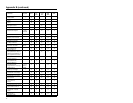
Pin Assignments for the PowerLink Cable
The MS7120 scanner interfaces terminate to a 10-pin modular jack.
Connect the 10-pin modular plug of the PowerLink cable into the jack
then connect the other end of the PowerLink cable to the host. (Refer to
page 6 for details). Due to the variations in current supplied by the many
available PC’s, Metrologic suggests the use of an external power supply.
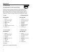
“9" OCIA “11" IBM 46XX/RS-232*
PIN FUNCTION PIN FUNCTION
1 Ground 1 Ground
2 RS-232 Transmit Output 2 RS-232 Transmit Output
3 RS-232 Receive Input 3 RS-232 Receive Input
4 RDATA 4 RTS Output
5 RDATA Return 5 CTS Input
6 Clock in 6 DTR Input
7 Clock out 7 IBM 46XX Transmit
8 Clock in Return/Clock out Rtrn 8 IBM 46XX Receive
9 +5VDC 9 +5VDC
10 Shield Ground 10 Shield Ground
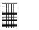
“67" RS-232/LTPN* “41" RS-232/LTPN
PIN FUNCTION PIN FUNCTION
1 Ground 1 Ground
2 RS-232 Transmit Output 2 RS-232 Transmit Output
3 RS-232 Receive Input 3 RS-232 Receive Input
4 RTS Output 4 RTS Output
5 CTS Input 5 CTS Input
6 DTR Input/LTPN Source 6 DTR Input/LTPN Source
7 Reserved 7 Reserved
8 LTPN Data 8 LTPN Data
9 +5VDC 9 +5VDC
10 Shield Ground 10 Shield Ground
*Preliminary
Options listed are program/cable selections